MapMyVisit – Email console manual

Introduction

MapMyVisit is Guide ID’s marketing platform, intended to be used by your visitors. They register their Podcatcher at the beginning, during, or at the end of the tour via a console by entering their email address. The Podcatcher saves which objects are and aren’t visited, even if they’ve been visited after using the console. After their visit the visitors receives an email thanking them for their visit and showing them a link to their personal page within MapMyVisit where they can re-experience the tour.

The visitor can use their personal page to view and listen to tours again. You are also able to place strategic links to your homepage, other websites for more information, your web shop, events page, ticketing page, et cetera on these personal pages. All of these links are placed to created more traffic to your other webpages, offer the visitor even more information and to increase visits and revenue. Links to your web shop can be to relating products and merchandise. Visitors’ email addresses are saved within the MapMyVisit platform, on Guide ID’s servers. You can contact them through Guide ID, but please note that we will not share these contact details with you directly because of the EU General Data Protection Regulation (GDPR). For this reason it’s also not necessary to sign a data processing agreement when you use MapMyVisit.

Social media is also a big part of MapMyVisit. Via MapMyVisit visitors can follow you on Facebook and Twitter with the click of a button. It’s also possible to share or post an individual part of the tour to their own personal page for all their contacts to see. We also add a button linking the visitor to your friends page or newsletter page. Final results: extra promotion, more branding, more visitors and extra revenue streams.

The MapMyVisit console

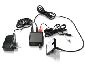
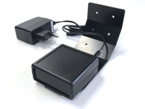
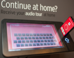
The MapMyVisit console – the rectangular device with a touch screen and an opening for a Podcatcher – is simpler than you might expect. The process is as follows:

  • Once it’s plugged in to a power outlet for the first time, it’ll need some touch screen calibration.
  • Then some settings need to be configured, such as which languages should be presented while idle.
  • After setting it up, the console will wait for a Podcatcher to be inserted into the slot. While waiting, it will cycle through the available languages on its display with instructions for the visitor on how to operate it.
  • When a Podcatcher is inserted, it will prompt the visitor with our privacy policy, which the visitor can (but generally doesn’t) read up on how Guide ID processes their personal data. If you’d like to read it, click here.
  • If the visitor doesn’t accept the privacy policy, the console will ask the visitor to remove the Podcatcher; if they do accept, the visitor can enter their e-mail address, double-check, and confirm it.
  • The console will then store the e-mail address on the Podcatcher itself. When the Tour concludes and the Podcatcher is handed in and synced, the visitor will receive an e-mail from MapMyVisit with a link to their personal page, where they can experience the Tour again.

Note: MapMyVisit will only show Tours and Stops that have MapMyVisit enabled on them. See the Portal section below.

As you can see – fairly straightforward. The console does not need an internet connection for it to do its job properly. If you’d like to test it, you can do so by simply listening to your Tour with a Podcatcher and entering your (work) email address.

Installation (hardware)

When you get your MapMyVisit console, all you need is a spot you want the console to be, a nearby power outlet, and a few minutes to configure the settings.

If you’d like to just change the available languages, simply reboot the console and skip to step 2.

Step 1. Connect the console and calibrate it

  1. Connect the console to the power outlet. It will automatically switch on.
  2. Complete touch screen calibration by selecting the target icon () in all 4 corners and the center. The console will reboot.

Step 2. Language selection

  1. Switch on the console (or wait until it has rebooted).
  2. Place a Podcatcher into the console.
    Note: the Podcatcher has to have been activated by a Start IDentifier (it must have started a Tour in any language).
  3. Agree to the privacy policy by pressing the arrow to the right.
  4. When asked for an e-mail address, enter “settings”. A screen should open as the last letter is typed.
    Note: Typing “settings” to open the menu only works in the first minute after starting the console.
  5. The settings screen shows all available languages. To make changes, you must first clear the active language settings by pressing the recycle bin icon at the bottom left.
  6. Now you can add languages as you like. The selected languages are shown in order at the bottom of the screen. The order in which languages are added matters, as that dictates the order in which they show up on the console while it’s idle. To navigate through the list you can use the arrow icons at the top and bottom of the screen. To add a language, first select it and then press the check mark on the right-hand side.
  7. When all languages have been added in the desired order, you can save the settings by pressing the save icon ().
  8. The languages are now saved and you will return to the main screen. The console is ready to use.

Getting the Tour ready in the Portal

Note: The content made available on MapMyVisit is largely identical to the content in the Podcatcher App, so if you’ve made content for one, it should be mostly done for the other as well. Check the Tour’s Publish page to be sure.

To start off, the Tour you want to have available for the MapMyVisit platform will have to be made available for it. In the Tour General screen, tick the box next to MapMyVisit if it isn’t enabled already and click Save. When you make a new Tour, you can also tick the box in the “Add Tour” popup. This, as you would expect, makes the Tour show up in MapMyVisit if a visitor has used the MapMyVisit console and left their email address. However, the Stops also need to be made available. Keep in mind that you usually don’t want all of the Stops to be visible in MapMyVisit as they would be redundant – such as the language selection Stop or the one for invalid IDentifiers.

Stops can be identified at a glance in the Stops list, with the Availability column. A grey “MMV” icon means it won’t be available in MapMyVisit, a blue one means it will be. Clicking on this icon will also take you to the Stop General screen, where you can toggle the MMV availability on or off.

The 4 default Stops

You will also find 4 default MMV Stops in your new tour;  The first stop MMV00 Instructions contains an audio file to which you can add a normal IDentifier (trigger) which explains to your visitors what MMV does. You can use this Stop but are not obligated to use it.

The other 3 Stops contain audio instructions for the console for which you have to add the complementary triggers. To add the right trigger you need to select edit trigger > add > show more > email console and then select the right event;

  • Stop MMV01 Activation unsuccessful (=registration was aborted partway through the process > select ‘Not completed’
  • Stop MMV02 Activation successful (=registration was completed successfully > select ‘Completed successfully’
  • Stop MMV02 Activated using blank email (=registration was completed, but no e-mail address was entered> select ‘Completed with blank email’

For a Tour to be ready for MapMyVisit, it should have the following:

If you’re ever unsure whether you’ve added all the content you need to make a successful MapMyVisit Tour, check out the Tour Publish screen. You’ll find a summary of all the content a visitor should be able to expect from a MapMyVisit page and whether said content is there or not.

AV-Sync manual

1. General

1.1. What can you do with AV-Sync?

Using AV-Sync, you can play audio on the Podcatcher synchronized to a video playing on a screen. This way multiple visitors can simultaneously watch the video on the screen and listen to the audio (in their own language) on the Podcatcher. There is no limitation to the number of visitors watching the video.

1.2. Package contents

AV-Sync IDentifier
This is the point of activation used for visitors to aim the Podcatcher at.

AV-Sync box
The AV-Sync box provides the AV-Sync IDentifier with the proper signals to transmit to the Podcatcher, such that the correct audio fragment is played on the Podcatcher at the right time.

5V-power adapter (narrow connector)
The power adapter provides the AV-Sync setup with power.

Audio cable
The audio cable connects the media player (refer to 1.3) to the AV-Sync box. The cable has a 3.5mm jack plug on one end and two RCA connectors on the other.

RCA cable
The RCA cable connects the AV-Sync box with the IDentifier.

1.3. Further requirements

1.3.1. Standard

Screen or projector (not included)
A television or other type of screen, suitable of displaying your video.

Media player (not included)
A media player suitable for playing your video. The media player requires an ‘audio out’ connector to connect to the AV-Sync setup. If desired, it must be able to play the video in a loop. The media player plays the video on the screen and/or projector, and sends the audio signal from the AV-Sync track to the AV-Sync box. Guide-ID recommends using a Brightsign media player.

Video content (not included)
The original video, combined with the AV-Sync track.

Audio content (not included)
The original audio track of the video to play, converted to MP3 format. Recommended encoder settings: 64 kbps, mono, 48 kHz, -1dB peak level. Different MP3 bitrates as well as stereo can be supported.

AV-Sync video tool (downloadable)
To prepare the audio and video content to use with AV-Sync you can use the AV-Sync video tool.

1.4. Overview of the AV-Sync box

Rear view


Front view

Address
These DIP-switches can be used to set the IDentifier code that the AV-Sync Box transmits.

Error LED (red)
The red LED blinks when an invalid AV-Sync track is received from the media player. If the LED lights up continuously, no signal is being received at all.

OK LED (green)
The green OK LED blinks when a valid AV-Sync track is received from the media player.

Gain knob
Using the turnable Gain knob, the incoming signal from the media player can be amplified. The signal is amplified by turning the knob to the right.
Note: Try setting the gain as low as possible (knob turned to the left).

Audio In connector
The media player connects to the AV-Sync box on this connector.
Note: Connect the red RCA plug of the audio cable. The white connector can be left unconnected. The AV-Sync box requires only mono audio.

IR Out connector
This connector is used to connect the supplied AV-Sync Identifier, using the RCA cable.

ON LED (yellow)
The yellow LED lights up continuously if the AV-Sync box is powered.

5V DC connector (narrow plug)
The supplied 5V power adapter connects to the DC connector to power the AV-Sync box.

2. Installation

2.1. General device function

The media player plays the video on the screen in the exhibition. It simultaneously sends the AV-Sync track to the AV-Sync box. The box combines the signal with a unique IDentifier code and transmits the signal in infrared using the AV-Sync IDentifier. Any Podcatcher receiving the signal translates the IDentifier code to the audio fragment to play, and translates the AV-Sync signal to the offset in time where the video is currently at. This way it plays the audio synchronously with the video playing on the screen.

A single signal suffices for the Podcatcher to play the audio for the entire video in sync. It is not required to keep aiming the Podcatcher at the IDentifier.

2.2. Media file preparation

Two steps are required to prepare your video for use with AV-Sync:

  1. Prepare the video file (replace the audio with the AV-Sync track). The video file will play on your mediaplayer.
  2. Prepare the audio file (split off the audio from the video to a MP3 file). The audio file will be uploaded in the TourEditor to be played on the Podcatcher.

Creating these files is an automatic process when using the video tool:

https://help.guideid.com/downloads/AV-Sync_Video_Tool_0.4.exe

To create the required output files in the same directory as the input file, just drag and drop the video on the tool.

Note that when both the mediaplayer and Podcatcher are setup to automatically restart the video, in most cases you will need to extend the audio. To do this select the advanced checkbox, and change the value at the ‘extend’ input accordingly.

For more information on the usage of the tool, please refer to the following page:

https://help.guideid.com/kb/av-sync-media-file-preparation/

2.3. Configuration in the TourEditor

This part of the installation requires the online TourEditor.

  1. Log in to the Portal, click on the TourEditor icon, and choose the Tour you’d like to add AV-Sync to.
  2. Make a new Stop (or choose an existing one) and go to the General tab.
  3. Tick the “AV-Sync” box and save.
  4. Go to the Stop’s Clips.
  5. Edit the first Clip, and upload the audio as appropriate for each language.
    • Use the audio file that has been split off from the video (see 2.2).
  6. In most cases, the video will loop, so the audio should as well. In the Clip flow editor, add an “auto continue” connection from the clip to itself to make it loop on the Podcatcher as well (refer to the image on the right).
  7. Configure the Stop Trigger by adding an AV-Sync IDentifier to the Stop. Read more about Triggers here.
    • For regular AV-Sync, the IDentifier code ranges from A0:01 to A0:7F.  You can choose a code and set the DIP switches on the AV-Sync IDentifier (or vice versa).
    • For AV-Sync in flexible mode, the IDentifier code ranges from A1:00 to A1:FF. The exact code depends on which track the video sends out to the AV-Sync IDentifier. You can choose the code during media file preparation in the AV-Sync tool.
    • For a full list of codes with DIP-switch settings, click here: AV-Sync DIP-switch settings
  8. If required, fine-tune the Audio Video Sync Offset on the Clip Advanced tab. This is normally not required, you can leave it at the default value of 0. By adjusting the offset, you can compensate for any delays that are introduced in the video stream.
  9. Publish the Tour and Sync so the Podcatcher will sync the content on to its SD card.

2.4. Installing the AV-Sync set

  1. Connect the media player to the screen or projector. This is usually done with a HDMI cable. Follow the instructions provided with the media player.
  2. Connect the AV-Sync box.
    • Connect the 3.5mm audio jack of the provided audio cable to the ‘audio-out’ connection of the media player;
    • Connect the red RCA connector on the other end (the right audio channel) to the AUDIO IN connector of the AV-Sync box.
      Notice: Do you want audio to play at the screen (not just on the Podcatcher)? Then connect the white RCA connector of the audio cable to the screen or amplifier.
      Notice: Don’t extend the audio cable between media player and AV-Sync box. This will cause signal degradation and may cause the AV-Sync box to be unable to decode the signal.
  3. Configure the IDentifier code on the AV-Sync box.
    The AV-Sync box can be assigned a fixed IDentifier code (regular mode), or can be configured to pass-through the IDentifier code from the video that is being played (flexible mode). The DIP switches are used to configure both the mode and the fixed address (if applicable).
    • For regular AV-Sync move the ADDRESS pins to the binary orientation that matches the last three digits of the code assigned in the TourEditor. For example, if the code is A0:01, the leftmost ADDRESS pin is moved to the upper position, all others are low. If the code is A0:02, the second pin from the left is the only pin in the upper position.
    • When using AV-Sync in flexible mode move all ADDRESS pins to the upper position. The AV-Sync box now expects to receive the IDentifier code from the AV-Sync track encoded in the video. This allows for playback of different videos on a single AV-Sync box (where each video contains a different AV-Sync track).
    • After configuration of the AV-Sync box IDentifier code, the device must be restarted by briefly disconnecting the power and reconnecting it.
  4. Connect the AV-Sync IDentifier with the provided RCA to the IR OUT connector on the AV-Sync box. The RCA can be extended if required.
  5. Connect the power adapter to the 5V DC connector on the AV-Sync box and plug it in to a main power outlet (100-240V AC / 50-60Hz)
  6. Place the AV-Sync box and IDentifier close to the screen displaying the video, to make it intuitive for the visitors to use it. Make sure the connecting cable and AV-Sync box are properly installed out of view, but still reachable.
  7. Test the video.
    • Start the video on the media player and check if it is properly displayed on the screen.
    • Check the volume of the media player to be unmuted and not too quiet.
    • Turn the GAIN knob on the AV-Sync box all the way down (counter-clockwise). Subsequently slowly turn it up (clockwise), until the green light starts blinking.
  8. Test the audio.
    • Point an activated Podcatcher to the IDentifier. Wait for the ‘beep’ indicating activation, and listen to the Podcatcher to confirm that the audio of the video is being played.
    • If the Podcatcher won’t play the clip, check if the green LED on the AV-Sync box blinks periodically. If not, try to exchange the red and with RCA plugs of the audio cable connecting to the AV-Sync box, and test again. If the problem persists, confirm the IDentifier code and sync state in the TourEditor.

3. Usage

The visitor can use the AV-Sync simply by pointing the Podcatcher at the AV-Sync IDentifier, just like any other IDentifier.
He or she will hear the audio synchronized to the playing video and in their own language, regardless of how far the video playback has progressed.

4. Fine tuning

4.1. Offset correction

Our AV-Sync solution will play audio on the Podcatcher lip-sync to the video, if the original audio would play in sync in the same setup (i.e. instead of the AV-Sync track, plays the original audio).

In some cases this is not the case, most notably when the video stream gets delayed in for instance a 4K television screen, but the audio stream is taken directly from the mediaplayer. It is advisable to avoid these kind of setups by using the audio output from the television screen. If this is not possible, if it for instance doesn’t have the right connection, you can resolve the delay in the tour editor.

Offset correction consists of two steps:

  1. Measure the time difference between audio and video before the clip restarts. You can measure it manually, or use AV-Sync Testmode.
  2. Adjust the slider “A/V Sync Offset” in the tour editor

4.2. Loop correction

If both the mediaplayer and the Podcatchers have been configured to automatically restart the video, keeping lip-sync audio may require applying a loop correction. The reason for this is that in most cases, the Podcatcher is quicker to restart the audio than the mediaplayer is to restart the video, causing them to lose perfect sync, if visitors are out of range of the IDentifier. Note that applying loop correction is not required when using Long Range mode or Interactive mode, where visitors remain in range of the IDentifier. The audio will in these cases automatically re-sync when the clip restarts.

Loop correction consists of two steps:

  1. Make sure audio and video are in perfect sync before the clip restarts
  2. Measure the time difference between audio and video after the clip restarts. You can measure it manually, or use AV-Sync Testmode.
  3. Adjust the slider “A/V Sync Loop time” in the tour editor

5. Troubleshooting

5.1. Should the AV-Sync IDentifier not work properly, please check the following first:

  1. Is the audio cable properly connected to the AV-Sync box and the media player?
  2. Is the RCA cable properly connected to the AV-Sync box and the IDentifier?
  3. Are the power adapters properly connected to a power outlet on one end and the AV-Sync box and media player on the other?
  4. Does the video being played have an AV-Sync track playing on the right-hand audio channel?
  5. Is the AV-Sync IDentifier code properly set on both the AV-Sync box as well as the TourEditor?
  6. Have you activated the Podcatcher with a Start IDentifier?
  7. Has the Podcatcher been synchronized with the correct content?

If that didn’t solve your problem, restart the AV-Sync box by unplugging the 5V power adapter and plugging it back in after half a minute or so. Sometimes restarting the media player also helps.

5.2. Should the AV-Sync IDentifier still be throwing a temper tantrum, check the following:

The yellow LED isn’t lighting up

  • The 5V power adapter isn’t connected to a proper power outlet, or
  • Its cable isn’t properly connected to the AV-Sync box, or
  • The adapter broke.

Find a working power outlet or replace the 5V power adapter.

The green LED is blinking, but the Podcatcher isn’t responding

  • Is the RCA cable properly connected to the IDentifier? You can try squeezing the connectors a little bit to make better contact.
  • Has the Podcatcher been activated with a Start IDentifier? If not, try activating it and trying again. You can also test with a different Podcatcher to verify.
  • Has the Podcatcher been synced with the correct content? Try syncing manually and try again.

The red LED is blinking

The AV-Sync box is receiving a signal, but not a proper time code. Lower the volume of the media player by 20%. Restart the AV-Sync box by unplugging the power adapter and plugging it back in. Reconnect the audio cable between the media player and the AV-Sync box. Turn the Gain knob until the green light starts lighting up. Test the audio output of the media player with headphones or speakers to check if you can hear the AV-Sync track (beeping noises at regular intervals). If you don’t hear the beeps, the AV-Sync track isn’t added to the video or the audio output isn’t selected on the player. Alternatively, the audio track was added to the left channel, in which case you can swap the white and red RCA plugs.

The audio plays, but always from the start of the video

Make sure the Stop is in AV-Sync mode in the TourEditor, publish and try again.

5.3. Try the Troubleshooter

To try to determine the cause if any problem, you can try the AV-Sync troubleshooter:

https://help.guideid.com/kb/av-sync-troubleshooting-en/

Syncconsole Specifications

Introduction

To synchronize content and usage data of the Podcatchers, a PC needs to be set up as a Sync Console near/at the handout desk which is connected to the Dockingstations and Internet. We will provide this PC to you, but if you need an extra Sync Console installed (for instance in the office or at a partner) you can  install our synchronization software on a regular PC. Below you find the specifications a Sync Console must meet to work properly.

Specifications

The computer that will be set up as Sync Console must meet (or exceed) the following specifications:

  • Any new PC you find in a store is more than likely good enough.
  • Operating System: Windows Vista or Windows 7 (32-bit and 64-bit editions are both supported), Windows 8 (32- or 64-bit), Windows 10 (32 or 64 bit).
  • We recommend buying a (mini)computer or laptop that still has USB 2 connections to connect the USB HUBs or Docking Stations to, we have seen problems with USB 3 connectors (usually USB 2 connectors in a computer are black and USB 3 ones are blue).
  • Do not connect more than 30 Docking Stations (or 300 Podcatchers) to a single sync PC.
    • When using USB hubs, connect the Docks only to the hubs, and the hubs only to the computer. Don’t plug hubs into other hubs, as we’ve experienced a lot of trouble with this in the past. If you decide to do this regardless, please mention this whenever you contact us for support on sync issues.
  • The PC needs to have an ethernet (wired) connection, only wifi is insufficient.
  • Internal memory (RAM): At least 512 MB.
  • Storage space (hard drive): At least 1 GB. It is strongly recommended to take a much larger margin in the amount of free space; preferably upwards of 100GB to allow Windows to continue installing updates for a long while.
  • USB connection: At least 1 free USB 1.1 port; typically you will have 10 Docks plugged into a USB hub, so the actual amount depends on how many Docking stations you have for a given Sync Console. Remember to limit the total number of docks connected to a single computer to 30.
  • The PC needs to be updated (automatically) with the latest Windows updates (using Windows Update).
  • The PC needs to be switched on 24 hours a day/7 days a week.
  • The PC needs to be connected to the Internet 24 hours a day/7 days a week.
  • The PC and connected Dockingstations need to be connected to the power 24 hours a day/7 days a week.
  • You need to have ‘Administrator’ privileges for the synchronization software to install.
  • Important for the IT Department; the Sync Console needs to be able to connect to our server via the website apps.podcatcher.eu on Port 80.

Note: The Podcatcher Sync software does not directly support connections to the Internet through a proxy server! There is a workaround for this, see the advanced setup page for more information.

Note: The Podcatcher Sync program does not run under Linux or MacOS.

Note: Never (!) use USB extension cords, only our provided USB cables (about 1.80m/6ft in length). If you need more length, place the sync computer closer or move the docks, you cannot extend the USB cables without running into serious sync issues that are very hard to diagnose and unsolvable for helpdesk.

Syncconsole Installation

Introduction

To synchronize content and usage data of the Podcatchers, a PC needs to be setup as a Sync Console near/at the handout desk which is connected to the Dockingstations and Internet. We will provide this PC to you, but if you need  an extra Sync Console installed (for instance in the office or at a partner) or if you have to re-install your own PC, you can  set up an a regular PC following the steps below. Note: any computer used as a Sync Console must meet these specifications.

Installation

Before a computer can sync Podcatchers, it will need some software so it ‘knows’ how to work with the Guide ID servers and devices. There’s TeamViewer (1)  that lets you (and us) connect to the computer remotely (should it be necessary) and the Sync desktop application (2). Afterwards, you’ll need to associate the desktop app’s serial number with your Site (3) so the computer can synchronize your content.

Attentionif you have not yet received the Docking Stations, you can start the installation steps but you will not be able to complete step 3 because the activation code is not shown and/or the Sync program will say that the Sync service is not running. This is due to a limitation of the Windows driver model. Once you have connected the Docking station(s) and reboot the computer, the activation code will be displayed.

1. Guide-ID TeamViewer

In order for us to be able to help you remotely, you have the option of installing the TeamViewer Host program. Guide-ID can use this program to help you, if there are any problems during the installation of the synchronisation program or at any other point down the line. Installing this program is optional, but we recommend it.

Note; We always recommend to connect the Sycconsole onto your ‘guest network’ so your internal network is protected at all times. Your system administrator will be able to do this for you as it’s their responsibility.  

  1. Download the program ‘TeamViewer_Host_Setup.exe‘.
  2. Find the file in your downloads folder, right-click on it and choose Run as Administrator. Contact your computer/network administrator to obtain these rights if you don’t have them.
  3. On the first screen click ‘Next’ .
  4. You will be asked how you would like to use the program, choose business/commercial and click ‘Next’.
  5. The license agreement will be shown, accept the agreement and click ‘Next’.
  6. You will be asked to choose a password, use the word Podcatcher and fill in a computer name, for example the name of your organization. If you have multiple Sync Consoles, we recommend naming them something descriptive like “Front desk” or “Podcatcher hand-out temporary tour” along with the name. You don’t have to tick the box for ‘add this computer to my list of computers’. Click ‘Next’.
  7. Click ‘Finish’ to complete the installation.
  8. After installation a screen with Your ID will be shown. Send an email to helpdesk@guideid.com with this number and a description of your computer (where it’s located for example).

2. Installation of the Podcatcher Sync application

  1. Download the program ‘Sync Installer.exe‘.
  2. Find the file in your downloads folder, right-click on it and choose Run as Administrator.
    1. Windows may ask you to download a required piece of software (the .NET Framework 3.5 runtime) before it’ll let you run the installer. If this happens, let it install the requirements, and try the installation again.
  3. Click the ‘Install button. The installation process will be run automatically. The installer will let you know when it’s done.
  4. As soon as the installation is finished you will see a green/white Podcatcher icon in your taskbar. If you double-click this icon you will see the sync program.
  5. The sync program should say ‘Warning – This Sync Console has not yet been activated yet!’. Beneath this message you will see an activation code. Copy this code by selecting as you would any other piece of text and press ctrl+c, or write this code down.

If you use a proxy server to connect to the Internet, check the article ‘advanced settings‘.

3. Activate your Sync Console online

  1. Go to the Podcatcher Portal and log in using your Podcatcher Portal account.
  2. Click ‘Sync‘ on the left-hand side of the page.
  3. Click the [ + Add Sync Console ] button to activate a Sync Console and to link it to your site.
  4. A popup window should appear with the following input fields:
    1.  First, select the Sync Console option and click Next.
    2. Sync Console Authentication Key, this is where you fill in the activation code that you copied/wrote down from the previous step.
    3. Sync Console Description, this is where you fill in a name for the Sync Console, for example, ‘Distribution point main desk’.
    4. Number of Docking Stations connected, this is where you fill in the amount of Docking Stations that are connected to the Sync Console. Note: It’s not the amount of Podcatchers!
  5. Add the Console by clicking [ Add Sync Console ]. The list of Sync Consoles should update and the new one appears.

If you have multiple locations where Podcatchers need to be provided with content, you can redo the steps mentioned here above at any location with any computer that complies to the Sync Console specifications. Every installation will have its own unique activation code that you can use to activate the location and to be able to see it in the online Sync App.

Should you run into problems installing the Podcatcher Sync application, try the Sync Console installation troubleshooting page.

Advanced Syncconsole setup

Introduction

Some computers need advanced settings to get the Podcatcher Sync program up and running. In this article you’ll find a couple of configuration options.

Proxy server

Some locations need to connect to the Internet through a proxy server. You can’t change this setting in the Podcatcher Sync program but you can still change it for the application. You can do this as follows:

  • Start the program ‘Notepad
  • Click File -> Open and navigate to the folder where the Podcatcher Sync program is installed. By default, this is ‘C:\Program Files\Guide ID\Podcatcher Sync.
  • Change the file types in the ‘open’-dialog from ‘text files (*.txt)‘ to ‘all files (*.*)
  • Select the file ‘Podcatcher Sync Service.exe.config‘ and open it. The extension .config might not be visible, if you click the wrong one it’ll show some garbled text. Should this happen, try again from the first step.
  • The file should open with readable text and start with <?xml version=”1.0″?>.
  • The last two lines of the file are currently </system.serviceModel> and </configuration>. Add the following information between the last line and the line before the last line:
<system.net>
 <defaultProxy enabled="true">
  <proxy bypassonlocal="true" proxyaddress="http://proxy.domain.org:8888/" />
 </defaultProxy>
</system.net>
  • Replace ‘http://proxy.domain.org:8888/‘ with the URL of your own proxy server.
  • Save the changes.
  • Restart the computer.

Warning IDentifier manual

Preventing your Podcatchers from going missing

Introduction

When a visitor uses a Podcatcher, you can expect them to return it after use. However, some visitors may neglect, or simply forget to do so. To lower the amount of Podcatchers ‘disappearing’ over time, there are two ways to activate a warning signal built into the Podcatcher to alert visitors they should return the device. The first is a special IDentifier called the Warning IDentifier, the second is a Podcatcher setting namely the “idle time Alarm”. You can use either, neither, or both, depending on what you think is appropriate.

Warning IDentifier

The Podcatcher can sound its warning signal when it receives a Warning IDentifier code. This is a special IDentifier that is typically placed near the building exit so visitors should be notified at the right time.

The advantages of this method are that Podcatchers are more likely to be dropped off over time (especially if you have a lanyard or wristband attached), and your staff will know to ask specific visitors to return the player before leaving the building. The disadvantage is that the IR signal doesn’t go through much in the way of cloth or leather, meaning Podcatchers won’t sound the warning signal if it’s been put in a bag or pocket.

Installation of the Warning IDentifier

CAUTION: Avoid looking directly into the Warning IDentifier’s front at close range! The infrared LEDs in the device are invisible to the human eye but are very bright, especially at close range.

Testing:

  1. Plug the adapter into a power socket and the adapter plug into the 9V DC input on the Warning IDentifier. Although there also is a RCA connector on the back, you only need to connect the 9V DC adapter plug and nothing else.
  2. The 2 LEDs on the back will blink green for a couple of seconds.
  3. Then the Warning IDentifier will start transmitting alarm codes. The top LED should be red and the bottom led should flash green every time an warning signal code is transmitted (about 4x per second).
  4. Take a Podcatcher from the Docking Station. The warning signal should sound when you are in range of the Warning IDentifier. It will sound for about 120 seconds. You can stop the warning signal sound by pressing any of the buttons on the Podcatcher, but when you are still in range it will sound again!

Configuration:

You can change the Warning IDentifier transmission power by setting the red/white switches at the back of the device.
The change takes place immediately and each increase adds about 2-3 meters of range.

Switch 1 up, all others down = 25% intensity

Switch 1 and 2 up, all others down = 50% intensity

Switch 1, 2 and 3 up, all others down = 75% intensity

Switch 1, 2, 3 and 4 up, all others down = 100% intensity

Mounting:

Podcatchers can only react to the warning signal when they are in visible range of the Warning IDentifier. The Waring IDentifier sends infrared signals and infrared cannot pass through objects,
therefore the Warning IDentifier works best when the Podcatcher is aimed directly at it. It is wise to place the Warning IDentifier in such a way that it is most likely to ‘reach’ a Podcatcher.

When mounting the Warning IDentifier near an exit, it is best to place it at the ceiling facing towards the visitors inside the building, so visitors that are walking towards the exit are most likely to get in range of the Warning IDentifier. When mounting near an entrance it is best to place the device in the other direction,thus facing outside of the building, because if it is facing inside, it is very likely that the Warnng IDentifier would trigger Podcatchers at the handout desk as well.

Please experiment which location and direction/angle works best to reach the Podcatchers, but not interfere with normal operations.

Warning signal after idle time

The Podcatcher can also sound an warning signal when it is engaged in a Tour but has not played audio for a while. By default this functionality is turned off, but you can set it up in the Site Podcatcher settings, under “Podcatcher idle time before alarm starts”.

The advantage of this method is that the warning signal will always sound after a while, unless properly handed in. The disadvantages are that if you set it to sound the warning signal too quickly, visitors may become annoyed; if you set it to sound the warning signal too late, the visitor may already be on the bus back home by the time it goes off. Further, if your site doesn’t collect Podcatchers in docks after visitors finish the tour (such as a drop-off box), they may start to produce a very annoying chorus over time.

Post-Alarm trigger

The Podcatcher can be made to play audio after sounding the warning signal using the Post-Alarm trigger in a stop. This will make the stop play its audio after the warning signal has stopped playing (either due to it playing for its full duration or a button being pressed). This is – as all content is – localized to the language of the tour.

Prevent missing Podcatcher

There are a number of ways to minimize the risk of losing Podcatchers. Below in the spec-sheet you’ll find a number of tips and best practices.

Prevent missing Podcatcher