You will always receive our Podcatchers and IDentifiers with our standard Guide-ID labels. But If you would like to customize your labels you can! To do so, you can make use of our new design and ordering method.
Depending on the country you are located in, you will receive either an accountora link to a unique page where you can design and order your labels. Customers located in the Netherlands and Belgium will reveice an account from our Customer Support department. Customers located in other countries will be able to access their own unique page with a link they will receive from our Customer Support department.
Within this account / or on this page you can create, save, order and re-order your designs now and in the future. And you will also be able to order our standard Guide-ID labels and various StartIDentifiers labels you might need.
If you are already our customer and would like to order new or additional labels, you will also be able to use our new design and ordering method from now on! Please contact our Customer Support at helpdesk@guide-id.com and we will make sure to set you up.
There are several ways to minimize the risk of losing Podcatchers. In this specsheet you’ll find a number of tips and best practices.
Other ways
When a visitor uses a Podcatcher, you can expect them to return it after use. However, some visitors may neglect, or simply forget to do so. To lower the amount of Podcatchers ‘disappearing’ over time, there are several ways to activate a warning signal built into the Podcatcher to alert visitors they should return the device.
Warning IDentifier
The Podcatcher can sound its warning signal when it receives a Warning IDentifier code. This is a special IDentifier that is typically placed near the building exit so visitors should be notified at the right time.
Warning signal after idle time
The Podcatcher can also sound an warning signal when it is engaged in a Tour but has not played audio for a while. By default this functionality is turned off, but you can set it up in the Site Podcatcher settings, under “Podcatcher idle time before alarm starts”.
The advantage of this method is that the warning signal will always sound after a while, unless properly handed in. The disadvantages are that if you set it to sound the warning signal too quickly, visitors may become annoyed; if you set it to sound the warning signal too late, the visitor may already be on the bus back home by the time it goes off. Further, if your site doesn’t collect Podcatchers in docks after visitors finish the tour (such as a drop-off box), they may start to produce a very annoying chorus over time.
Post-Alarm trigger
The Podcatcher can be made to play audio after sounding the warning signal using the Post-Alarm trigger in a stop. This will make the stop play its audio after the warning signal has stopped playing (either due to it playing for its full duration or a button being pressed). This is – as all content is – localized to the language of the tour.
When we receive a Podcatcher in need of repair, we will always try to transfer the label onto the new player first. Sometimes this is not possible, in that case you will receive a new player with our label. Of course, this also applies for IDentifier labels. It is therefore important for you to have enough labels in stock yourself to be able to change a label when necessary.
New or extra labels?
If you would like to order new or extra labels, please contact our Customer Support at helpdesk@guide-id.com
If you would like to design a furniture for our Podcatchers, you can choose between a design using loose Dockingstations or a design where you use a cabinet block which you slide into the furniture.
When you are designing a furniture this is what you need to keep in mind;
The design is of course very dependent on the number of Podcatchers that you want to supply to your visitors. (Make sure to think about the future, when you might want to add players).
Per 10 Podcatchers you will receive 1 Dockingstation
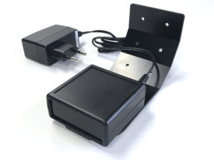
When designing for loose Dockingstations; each Dockingstation has its own USB cable (and power-adapter with older Dockingstations) which needs to be connected to the Syncbox. So make sure to keep enough space available behind the Dockingstations for these cables (and extension courts when needed)
Up to 10 Dockingstation (or 1 cabinet block) can be directly connected to one single Syncbox, which in turn needs to be connected to the internet. The cable length of the USB cable from each loose Dockingstation to the Syncbox is 90 CM, so the Syncbox needs to be placed near the Dockingstations. Because the USB cables also power the dockingstations, a Hub can not be used to extend the length of the cables.
When using a Cabinet block the cables are already connected inside the block and the Syncbox is placed in the back if the block (see the manual)
When designing for loose Dockinstations; keep room for the Syncbox(es). Depending on the set up, you will probably have to use multiple Syncboxes (100 Podcatchers can be connected to 1 Syncbox)
It is also important to take into account where you place the Syncbox because it must be easily accessible if you have to restart it.
In addition, it is also important that you have easy access to the back of the furniture unit, if there are problems with a USB cable / power adapters /extension cords / switch etc.
The entire setup must be connected 24/7 to power and a wired internet connection for the correct operation of the system.
Also make sure the furniture has enough possibilities to ventilate warm air.
Don’t place the top row with Dockingstations to high, otherwise you cannot see the lights (the status) of the Podcatchers
Don’t place the bottom row with Dockingstations to low.
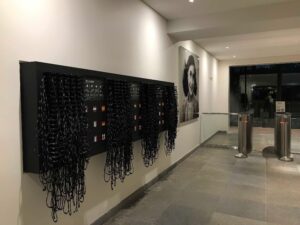
Each Podcatcher is equipped with a neck lanyard. When the Podcatchers are placed in the Dockingstations, the lanyards hang down. So if the bottom row is to low, the lanyards will hang on the floor.
We recommend to place the lowest row of Dockingstations at a height of at least 100 cm from the ground. That way they are still easy to access for infants and visitors in a wheelchair.
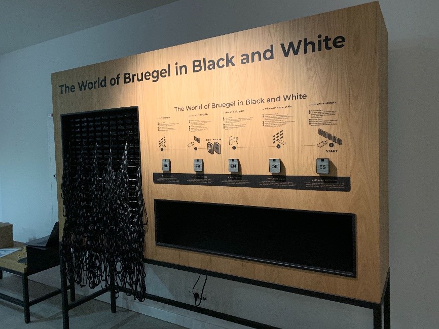
We have 4 info-graphics available that explain the handout of the Podcatcher which you can add to the (self-service) furniture if you like; https://help.guideid.com/kb/icons-for-signage/
Also important
We strongly advise not to use drawers in your furniture design for the distribution of the Podcatchers for several reasons; the USB cables (and power adapters) that are connected to each Dockingstation will be under tension constantly when sliding the drawers in and out. In addition, the cords can easily get stuck and you cannot properly detect wear on the wiring. Chances are also very high that cables are pulled from the Syncbox so no connection can be made when synchronizing, which in turn ensures that not all Podcatchers are synchronized
Take your visitor flow into account (with self-service, the amount of visitors able to access the furniture at the same time) and how you would like to lead them. When having one furniture for instance there are 2 flows; visitors who have just entered the museum and need to be able to easily access the furniture, to take out and activate a Podcatcher. While the second flow (visitors who are leaving the museum) must return their Podcatcher. These two flows should not interfere with each other.
Placement of the Start IDentifiers
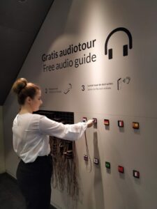
To activate a language, you need to point your Podcatcher at a Start IDentifier. These are always placed at (or near) the distribution point.
You can either integrate them in the furniture or make a separate board where people can activate their Podcatchers (so separate from the furniture). A reason to do so, could be the visitor flow, or because of limited space around the furniture.
If you do integrate them into your furniture, please make sure not to place them flat (with a table design) or underneath the last row with Dockingstations (with a wall design).
Other important information about placing your (Start) IDentifiers can be found here.
Casing of the Identifiers
If you prefer to place the Identifiers in a casing, please keep in mind that our Identifiers are equipped with Bluetooth functionality. The Bluetooth signal cannot be transmitted through metal. This means that Identifiers cannot be placed in a metal casing.
Sometimes, our Podcatchers need some extra attention, for example when they get into an errormode. If this is the case, the LED light on the Podcatcher will show you. Our new and updated manual will help you prevent Podcatchers going into an error state and explain what the LED light is telling you and which action to take. The manual combines the information in 3 languages; Dutch, English and French. User manual
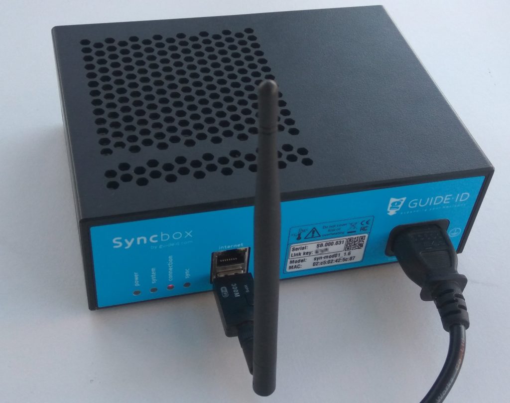
The Syncbox is a compact computer, designed by Guide ID to charge and synchronize Podcatcher audio guides. You can connect up to 10 dockingstations (100 Podcatchers) to one Syncbox.
We recommend using a wired network connection whenever available. In cases where it isn’t, but you have a WiFi network available, you can connect the Syncbox to it using a USB WiFi dongle.
Only specific types of dongles are supported, so please contact our helpdesk if you are in need of one. Configuration must be repeated for each USB dongle. If you have more than one Syncbox, you may be provided with a WiFi access point instead, to simplify the configuration and provide the best reception.
1.1. USB WiFi dongle
Connecting the Syncbox to WiFi using a USB dongle is an easy one-time process. Follow the steps below.
1. Insert the USB dongle into the front USB port that is below the Ethernet port, and startup you Syncbox. Note: Do not use any of the 10 USB ports on the rear of the Syncbox for the WiFi dongle. The device will not be found.
Step 1: Connect the WiFi dongle
2. Wait for about 2 minutes, until the connection LED starts flashing red. This indicates that the Syncbox has started a WiFi hotspot.
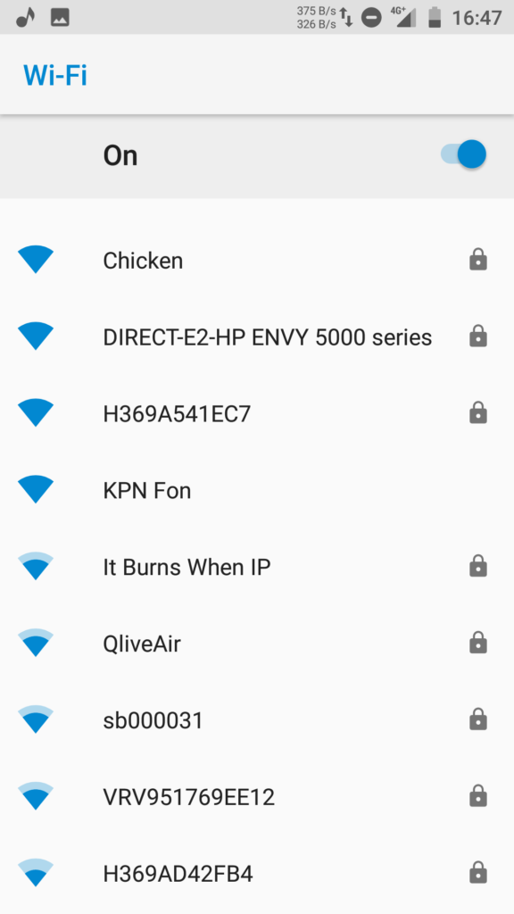
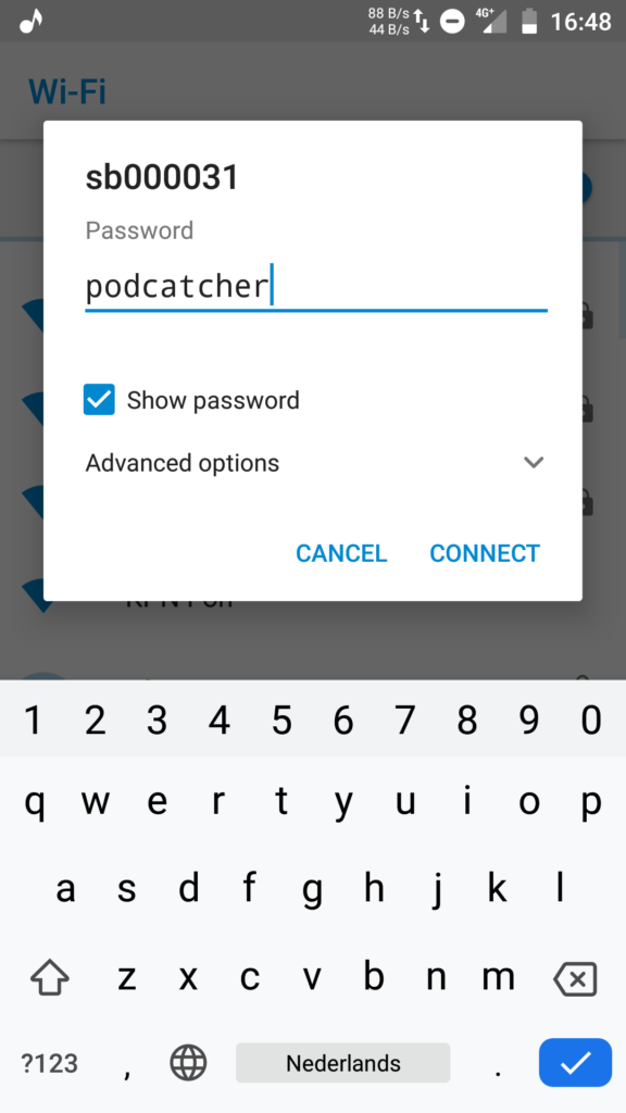
3. Search for WiFi networks on you phone (or another WiFi capable device). Select the network named after the label on you Syncbox, and connect to it. The WiFi password is “podcatcher”.
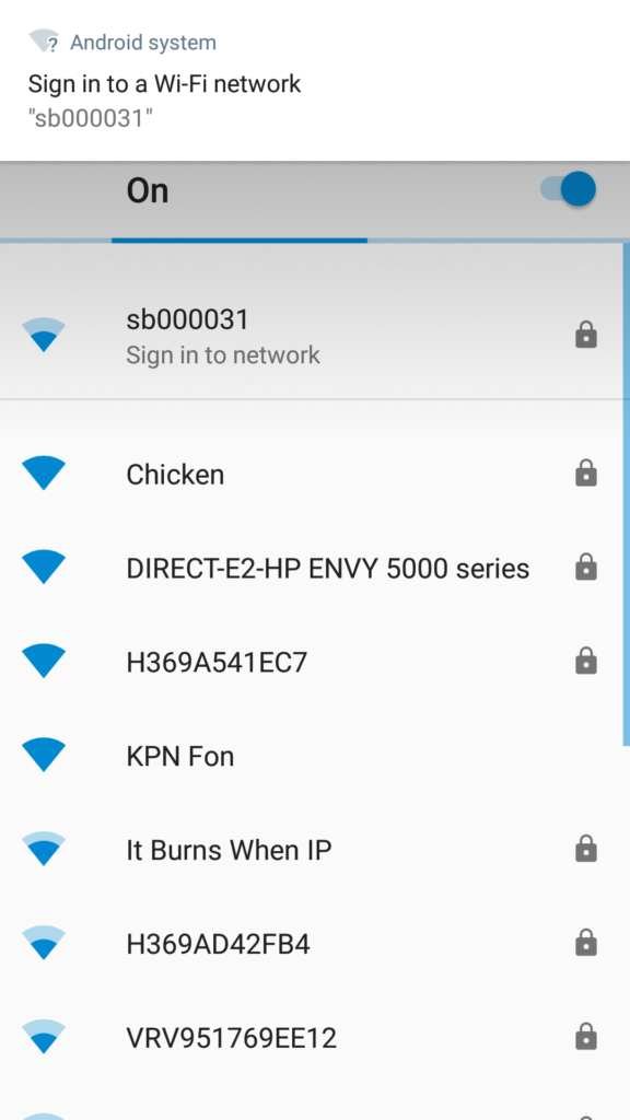
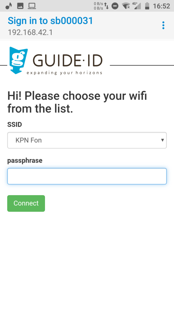
4. When you are connected to the hotspot, a popup should be shown: “Sign in to network”. Click on it to open the WiFi configuration page.
5. Select your WiFi network from the drop down list. Enter the passphrase, and click “Connect”. The WiFi hotspot will be disabled, and the Syncbox will connect to your WiFi network.
To check if the connection is succesfull, observe the connection LED. The LED should be blinking orange, and become green after about one minute. If there is an error connecting to the WiFi network, the LED will return to blinking red and the hotspot will be restarted. You can then go back to step 3.
1.2. WiFi access point
Instead of using a WiFi dongle for each Syncbox, it is possible to use an access point in client mode to connect many Syncboxes to your wireless network at once. The Syncboxes connect to the access point by means of Ethernet cables, and the access point is configured to connect to your wireless network. To help plan your setup, please contact our helpdesk.
Configuration using a WiFi access point is similar to the procedure for connecting a single USB dongle. But, you will only have to configure the access point.
2. Proxy server
On some locations it is required to access the internet through a proxy server. The Syncbox supports proxy servers through automatic and manual configuration. There are however some requirements on the type of proxy server used.
2.1. Proxy server requirements
Your proxy server must meet the following requirements:
Support HTTPS connections to websites. Or in technical terms: support the HTTP CONNECT method, where the proxy server sets up a direct connection between the client and the website. As most websites today use HTTPS, most proxy servers support this feature. Some proxy servers however require clients to install a special certificate, instead of using HTTP CONNECT. This is currently not supported by the Syncbox.
If your proxy server requires entering a username and password to access the internet, this is supported by the Syncbox, but currently only through the HTTP basic authentication scheme. Other existing types (e.g. HTTP Digest, HTTP NTLM and HTTP Negotiate) are currently not supported.
2.2. Automatic configuration (WPAD)
The Syncbox supports automatic configuration of a proxy server by means of the Web Proxy Auto-Discovery Protocol (WPAD). If your network is configured to support this, proxy server configuration of the Syncbox is done automatically and will work out of the box.
If your proxy server requires entering a username and password to access the internet, automatic configuration will normally not provide the Syncbox with these credentials. To enter them you would need to resort to manual configuration. As an alternative you can include the credentials in the the proxy URL in the PAC file. An example PAC file in this format is shown below.
function FindProxyForURL(url, host)
{
   return "PROXY username:password@192.168.1.1:8080; DIRECT";
}
Note: Including the username and password for the proxy server in the PAC file will make it available to all users on the network, unless access to the PAC file is regulated by for instance IP address. The MAC address of the Syncbox is printed on its label to allow to assigning it a specific IP address.
3. Manual configuration
Manual configuration of Syncbox network settings is possible using a USB mass storage device. Please follow the steps below.
3.1. Prepare the USB stick
Format a USB stick in FAT format.
Create a new text file on it named “config”. The file must not be placed within a directory.
Add configuration entries to the file as specified below.
3.2. Network configuration entries
The configuration file “config” can contain a combination of the following configuration entries, each on a separate line.
3.2.1. General
Clear all network profiles config_net_reset=1
Note: The reset can be combined with other entries and will be handled first.
3.2.2. Wireless LAN
WiFi ssid to apply settings to (if omitted, configure Ethernet) config_net_wifi_ssid=My WiFi Network
WiFi password to install config_net_wifi_pass=password
WiFi auth-alg: – open: Open System – shared: Shared Key config_net_wifi_auth=open
Note: Proxy configuration applies to wired Ethernet, unless it is combined with wireless LAN configuration entries. To manually configure a proxy server for WiFi, you must also manually configure the WiFi settings. If you have already used the hotspot method to configure WiFi, you must clear the existing profile using the reset option listed above.
Proxy server host config_net_proxy_host=192.168.1.1
Proxy server port config_net_proxy_port=8080
Proxy server username config_net_proxy_user=username
Proxy server password config_net_proxy_pass=password
3.3. Apply settings on a Syncbox
Using the following steps you can apply the configuration to a Syncbox. You can repeat these steps on multiple Syncboxes, using the same USB stick.
Power off the Syncbox, by holding the “Shutdown” button 10 seconds until the system LED starts blinking orange and finally switches off.
Insert the USB stick into the front USB port below the Ethernet connector. Note: Do not use any of the 10 USB ports on the rear of the Syncbox for the USB stick. The device will not be found.
Press and hold the “Shutdown” button for 10 seconds to start it in recovery mode. The Syncbox should apply the settings, and automatically reboot to normal mode. Note 1: Release the button when the system LED becomes orange. If you hold it too long it becomes red and will start in a different mode. Note 2: If applying the settings failed or no settings were applied, the Syncbox will stay in recovery mode and the system LED will stay red. In this case check the USB device, and restart at step 1 to retry.
Guide-ID B.V support the following payment methods:
Europe (accepting EUR and GBP) Guide-ID B.V. has a bank account with Rabobank IBAN (account number): NL27 RABO 0119642182 SWIFT (BIC): RABONL2U Please quote reference: Invoice number xxxxxx (see invoice for details)
United States (dollars) Guide-ID B.V. has a bank account with WISE Account number: 8311264538 Routing Number (ACH or ABA): 026073150 Wire routing Number: 026073150 Bank code (SWIFT/BIC): CMFGUS33 Address: 30 W. 26th Street, Sixth Floor New York NY 10010 Please quote reference: Invoice number xxxxxx (see invoice for details)
Check payments PLEASE NOTE: Check payment are NOT accepted and will not be processed.
If you have any additional questions, please send an email to: billing@guide-id.com