To synchronize content and usage data of the Podcatchers, a PC needs to be set up as a Sync Console near/at the handout desk which is connected to the Dockingstations and Internet. We will provide this PC to you, but if you need an extra Sync Console installed (for instance in the office or at a partner) you can install our synchronization software on a regular PC. Below you find the specifications a Sync Console must meet to work properly.
Specifications
The computer that will be set up as Sync Console must meet (or exceed) the following specifications:
Any new PC you find in a store is more than likely good enough.
Operating System: Windows 10 (32- or 64-bit), Windows 11 (32 or 64 bit).
We recommend buying a (mini)computer or laptop that still has USB 2 connections to connect the USB HUBs or Docking Stations to, we have seen problems with USB 3 connectors (usually USB 2 connectors in a computer are black and USB 3 ones are blue).
Do not connect more than 20 Docking Stations (or 200 Podcatchers) to a single sync PC.
When using USB hubs, connect the Docks only to the hubs, and the hubs only to the computer. Don’t plug hubs into other hubs, as we’ve experienced a lot of trouble with this in the past. If you decide to do this regardless, please mention this whenever you contact us for support on sync issues.
The PC needs to have an ethernet (wired) connection, only wifi is insufficient.
Internal memory (RAM): At least 512 MB.
Storage space (hard drive): At least 1 GB. It is strongly recommended to take a much larger margin in the amount of free space; preferably upwards of 100GB to allow Windows to continue installing updates for a long while.
USB connection: At least 1 free USB 1.1 port; typically you will have 10 Docks plugged into a USB hub, so the actual amount depends on how many Docking stations you have for a given Sync Console. Remember to limit the total number of docks connected to a single computer to 30.
The PC needs to be updated (automatically) with the latest Windows updates (using Windows Update).
The PC needs to be switched on 24 hours a day/7 days a week.
The PC needs to be connected to the Internet 24 hours a day/7 days a week.
The PC and connected Dockingstations need to be connected to the power 24 hours a day/7 days a week.
You need to have ‘Administrator’ privileges for the synchronization software to install.
Important for the IT Department; the Sync Console needs to be able to connect to our server via the website apps.podcatcher.eu on Port 80.
Note: The Podcatcher Sync software does not directly support connections to the Internet through a proxy server! There is a workaround for this, see the advanced setup page for more information.
Note: The Podcatcher Sync program does not run under Linux or MacOS.
Note: Never (!) use USB extension cords, only our provided USB cables (about 1.80m/6ft in length). If you need more length, place the sync computer closer or move the docks, you cannot extend the USB cables without running into serious sync issues that are very hard to diagnose and unsolvable for helpdesk.
To synchronize content and usage data of the Podcatchers, a PC needs to be setup as a Sync Console near/at the handout desk which is connected to the Dockingstations and Internet. We will provide this PC to you, but if you need an extra Sync Console installed (for instance in the office or at a partner) or if you have to re-install your own PC, you can set up an a regular PC following the steps below. Note: any computer used as a Sync Console must meet these specifications.
Installation
Before a computer can sync Podcatchers, it will need some software so it ‘knows’ how to work with the Guide ID servers and devices. There’s TeamViewer (1) that lets you (and us) connect to the computer remotely (should it be necessary) and the Sync desktop application (2). Afterwards, you’ll need to associate the desktop app’s serial number with your Site (3) so the computer can synchronize your content.
Attention: if you have not yet received the Docking Stations, you can start the installation steps but you will not be able to complete step 3 because the activation code is not shown and/or the Sync program will say that the Sync service is not running. This is due to a limitation of the Windows driver model. Once you have connected the Docking station(s) and reboot the computer, the activation code will be displayed.
1. Guide-ID TeamViewer
In order for us to be able to help you remotely, you have the option of installing the TeamViewer Host program. Guide-ID can use this program to help you, if there are any problems during the installation of the synchronisation program or at any other point down the line. Installing this program is optional, but we recommend it.
Note; We always recommend to connect the Sycconsole onto your ‘guest network’ so your internal network is protected at all times. Your system administrator will be able to do this for you as it’s their responsibility.
Find the file in your downloads folder, right-click on it and choose Run as Administrator. Contact your computer/network administrator to obtain these rights if you don’t have them.
On the first screen click ‘Next’ .
You will be asked how you would like to use the program, choose business/commercial and click ‘Next’.
The license agreement will be shown, accept the agreement and click ‘Next’.
You will be asked to choose a password, use the word Podcatcher and fill in a computer name, for example the name of your organization. If you have multiple Sync Consoles, we recommend naming them something descriptive like “Front desk” or “Podcatcher hand-out temporary tour” along with the name. You don’t have to tick the box for ‘add this computer to my list of computers’. Click ‘Next’.
Click ‘Finish’ to complete the installation.
After installation a screen with Your ID will be shown. Send an email to helpdesk@guideid.com with this number and a description of your computer (where it’s located for example).
2. Installation of the Podcatcher Sync application (Sync Console 2.x)
The Sync Console 2.x application is a Windows service that allows Podcatcher V3 hardware to sync with the PP4 Platform. It replaces the legacy Podcatcher Sync service.
The new service can be installed on Windows 10 or 11. If the legacy Podcatcher Sync is already installed, it will be automatically replaced.
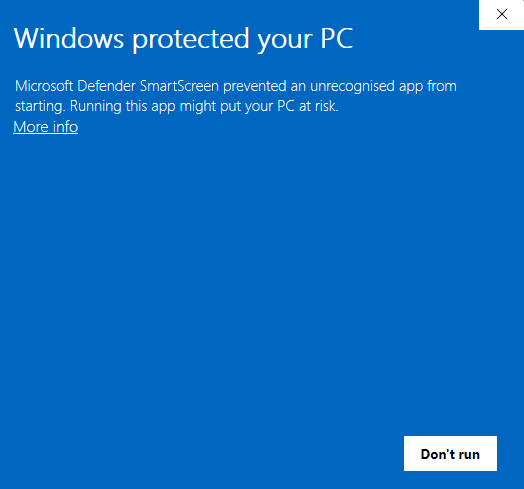
Download the msi installer from GuideID.SyncSetup and run it. Depending on your security configuration, a message similar to this may appear:
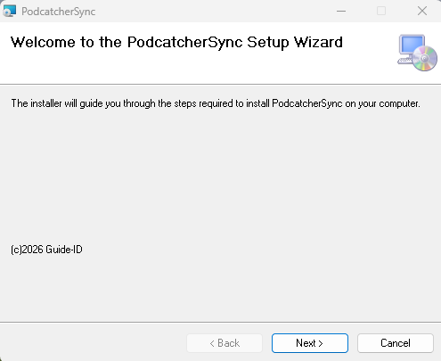
If the “Run anyway” button is already visible, click it. Else you need to click “More info” first and then click “Run anyway”. You will be greeted by the following screen:
Click “Next” to continue.
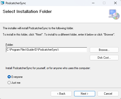
Select where to install the application. It is recommended to accept the default location. (Note: the contents of all Podcatcher audio tours will be stored here as well, so make sure there is enough space available.)
Make sure to select “Everyone” and click “Next”:
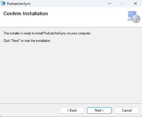
Click “Next”:
Click “Next”:
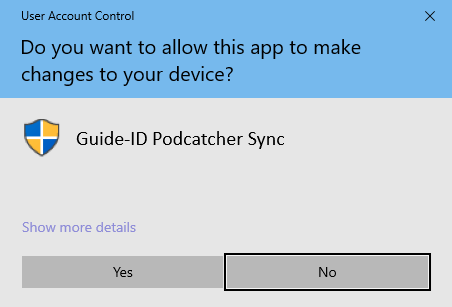
A warning similar to the one above may appear asking permission to make changes to your device. Click “Yes” or “Allow” or something equivalent to continue installation.
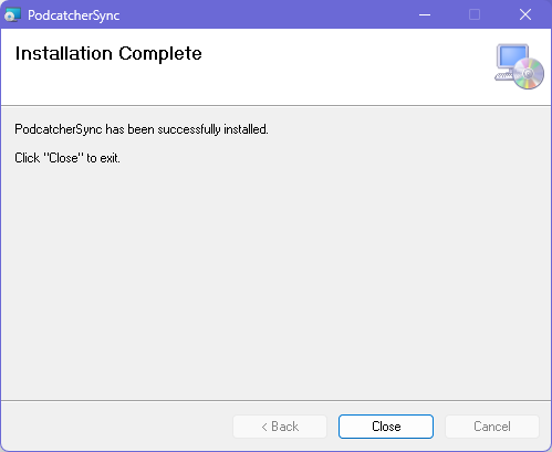
After the application has been installed, click Close.
Identifying the Serial Number and Authentication Key
If the Sync Console still needs to be registered in the Podcatcher Platform, you need to provide a serial number and authentication key.
This information can be retrieved by running the following command from an elevated command prompt (run cmd as administrator):
GuideID.PodcatcherV3Sync.exe -cmd info
The following information appears.
Guide-ID Podcatcher Sync Service version: 2.1.0.0 Sync Console Serial number: scXXXXXXXXXX Authentication key: XXXXX-XXXXX-XXXXX-XXXXX-XXXXX
Take note of the Sync Console Serial number and the Authentication key and enter them in the Platform when registering your Sync Console.
3. Register your Sync Console
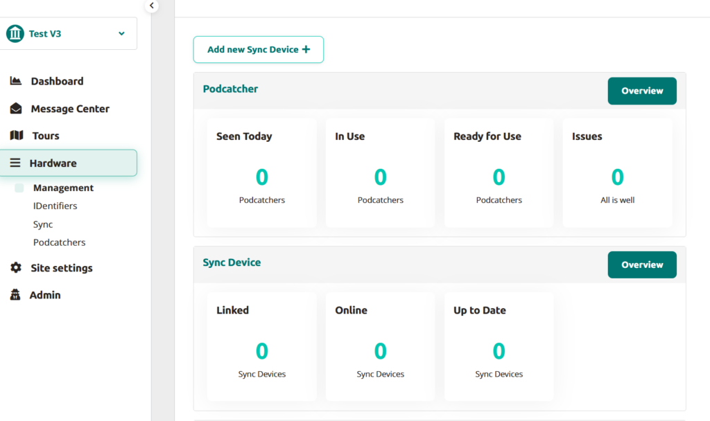
Go to the Podcatcher Platform and log in using your Podcatcher Platform account.
Click ‘Hardware →Sync‘ on the left-hand side of the page.
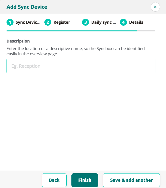
Click the [ + Add new Sync Device ] button to register a Sync Console and to link it to your site.
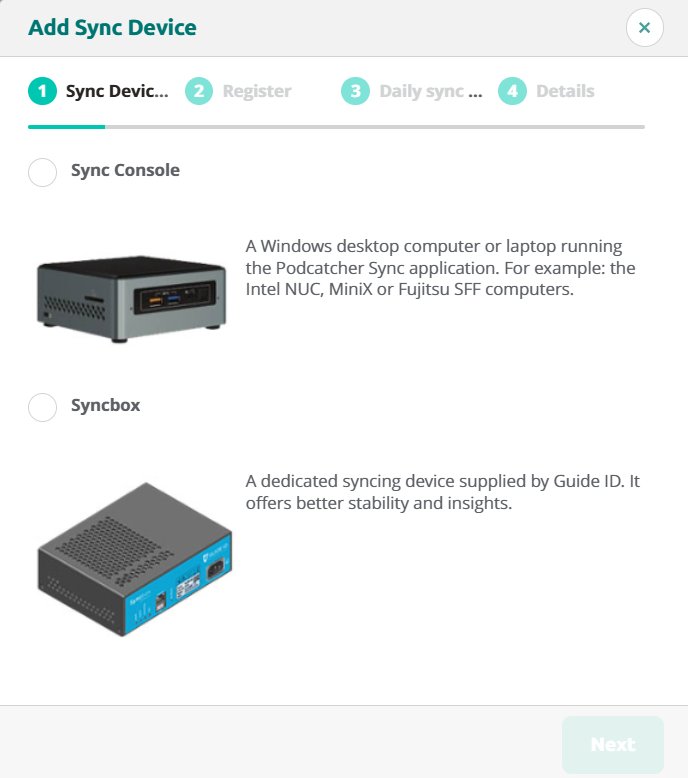
A popup window should appear with the following input fields:
First, select the SyncConsole option and click Next.
Sync Console Serial Number and Authentication Key, this is where you fill in the serial number and authentication key that you copied/wrote down from the previous step.
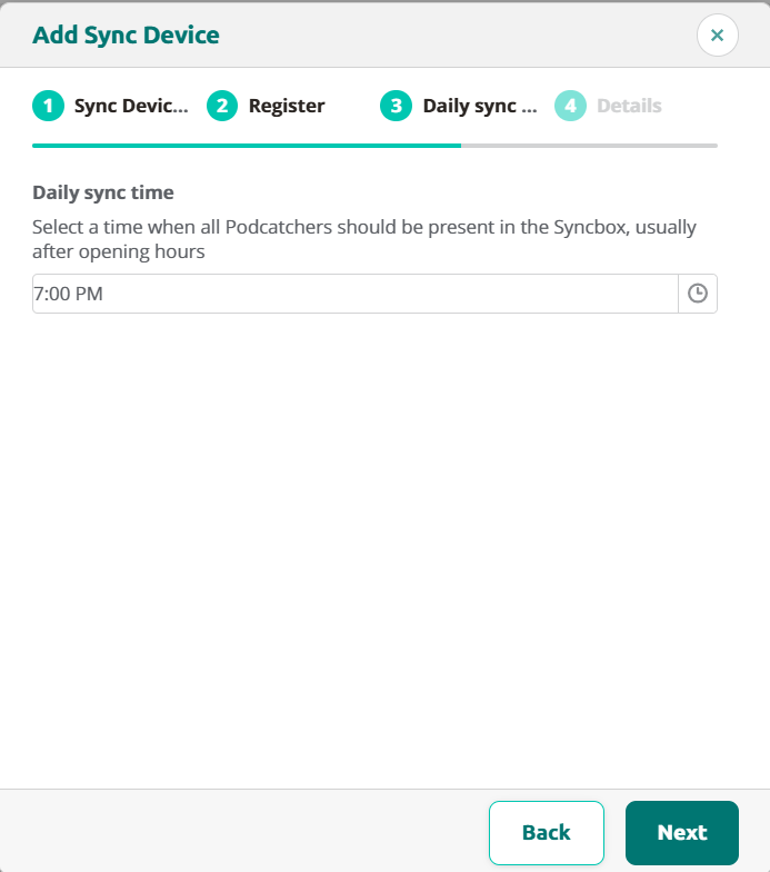
Sync Console Daily sync time, this is where you select a time when all Podcatchers should be present in the Sync Console, usually after opening hours.
Sync Console Description, this is where you fill in a name for the Sync Console, for example, ‘Distribution point main desk’.
Add the Sync Console by clicking [ Finish ] button. The list of Sync Consoles should update and the new one appears.
If you have multiple locations where Podcatchers need to be provided with content, you can redo the steps mentioned here above at any location with any computer that complies to the Sync Console specifications. Every installation will have its own unique activation code that you can use to activate the location and to be able to see it in the online Sync App.
When the audio tour isn’t working, there are a few things you should check.
Podcatchers
If a Podcatcher isn’t working as it should, we recommend reading this article instead. Most misbehaving Podcatchers can be brought back in line by synchronizing them.
IDentifiers
If a Podcatcher seems to not respond to one or more IDentifiers, there’s a few things you can try. First you have to make sure if you hear a beep when pointing the Podcatcher at an IDentifier.
The Podcatcher beeps when pointed at the IDentifier, and either plays the “Invalid IDentifier Stop” content or no content at all.
Make sure you activate a tour by pointing at a Start IDentifier before testing an Object IDentifier. And make sure the Stop you’re testing with is linked to the correct Tour. Read more about Start IDentifiers here.
Check if the content is published and synced.
Check if the code written on the back of the IDentifier matches the one linked in the TourEditor.
Check if the Stop has audio content.
Publish any unpublished changes in the Tour.
Sync the content onto the Podcatchers again to be sure.
If that doesn’t work, it’s possible (though rare) that the code the IDentifier sends out is different from what’s printed on the sticker. You can check this by using the Podcatcher to read the code to you. Here you can read how to do that.
The Podcatcher does not beep when pointed at the IDentifier.
This is usually a sign that the battery in the IDentifier is empty. Try with a few different Podcatchers to confirm that this might be happening (and isn’t just the Podcatcher’s fault), then replace the battery. If that doesn’t work, the IDentifier can be sent for repairs.
We hope to be helpful enough with this Knowledge Base, but it’s entirely possible you have a question that isn’t listed anywhere. Should that happen, contact us. We’ll be glad to help you get back up and running with the system.
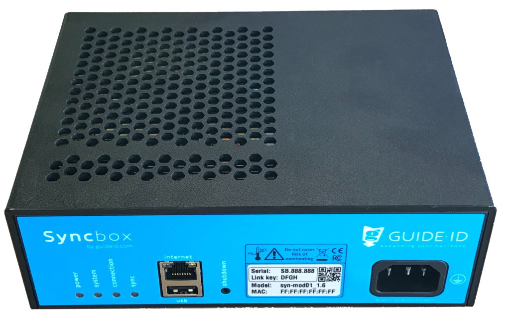
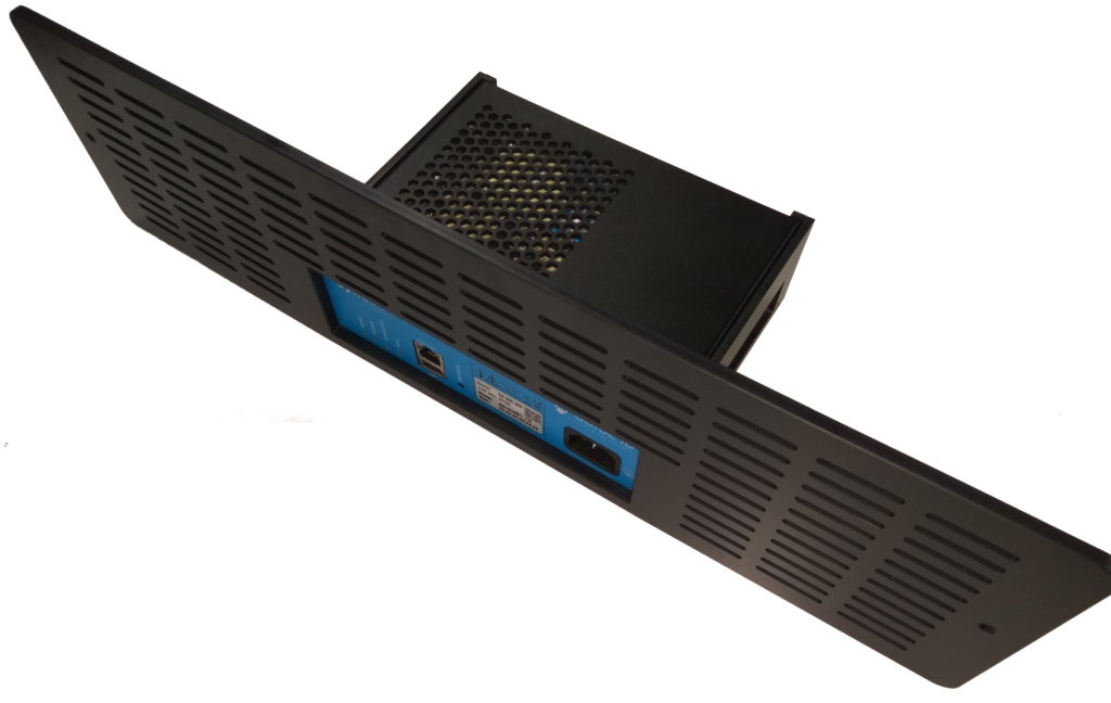
The Syncbox is a compact computer, designed by Guide ID to charge and synchronize Podcatcher audio guides. You can connect up to 10 dockingstations (100 Podcatchers) to one Syncbox. If you have more Podcatchers on location you will need multiple Syncboxes.
The Syncbox is IEC 62368 certified. However the following safety requirements apply:
Use the Syncbox only within the specified operating temperature range (0-50 C).
Do not cover the ventilation openings. Risk of overheating.
Use the provided AC power cable only.
Connect AC cable to an earthed mains socket outlet or extension cord.
Mains socket outlet must be easily accessible to allow disconnecting the cable.
Ethernet port is intended for LAN connection installed wholly within the same building structure.
The Syncbox contains a Lithium-Ion battery (750 mAh, 3.7V, AA format). The battery is IEC 62133 certified.
Caution:
Do not replace the battery. Risk of explosion if the battery is replaced by an incorrect type.
Disposal of the battery into fire or a hot oven, or mechanically crushing or cutting of a battery, can result in an explosion.
Leaving the battery in an extremely high temperature environment can result in an explosion or the leakage of flammable liquid or gas.
Subjecting the battery to extremely low air pressure may result in an explosion or leakage of flammable liquid or gas.
1.5. Requirements
Important: The Syncbox must be connected to power and internet 24 hours per day, 7 days a week.
To connect the Syncbox you will need:
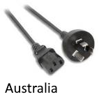
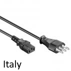
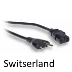
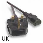
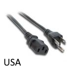
Available power outlet (country specific AC Power cord is provided)
Internet connection, by means of either:
Ethernet cable or free socket (CAT5 or CAT6 standard)
WiFi network (IEEE802.11n / g / b, 2.4 GHz bands)
1.5.1. Power
If power is removed, the Syncbox will continue on battery power for about half an hour. It will indicate this by beeping periodically. See Running on battery power.
1.5.2. Internet
If internet is disconnected, the Syncbox will remain functional for a maximum of 2 days. However contact with the Portal is not possible.
The internet connection has the following requirements:
Fully functional internet access to websites (HTTPS).
If you have multiple devices, a Router with DHCP is required. For multiple Syncboxes built into cabinets, a network switch is provided to make them share a single connection.
If you have a firewall, outgoing access to HTTPS (TCP port 443) is required. The Syncbox uses only outgoing connections on that port. No port forwarding is required for incoming connections. Whitelisted domains should include:
syncboxapi.guideid.com
syncboxlogs.guideid.com
syncboxdebug.guideid.com
Using an Ethernet cable is recommended above using a WiFi network. Connecting the Syncbox to your WiFi network requires manual configuration. Please refer to advanced network configuration.
Internet access through proxy servers is supported, but may require manual configuration. Please refer to advanced network configuration.
2. Installation
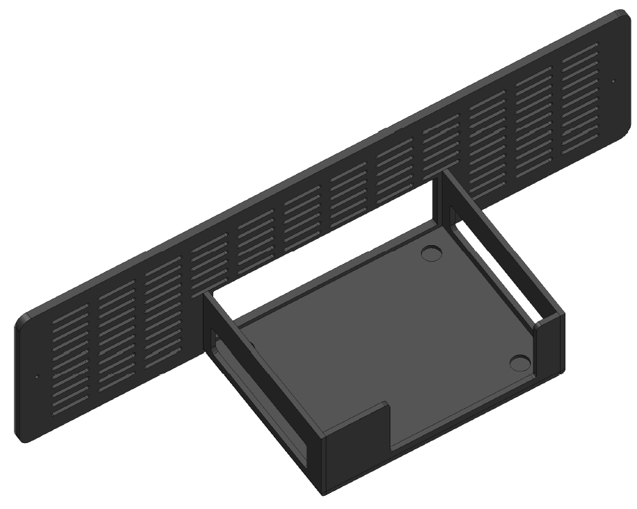
2.1. In a cabinet
On the rear of the cabinet, remove the cabinet holder (2 screws)
Place the Syncbox in the cabinet holder
Guide the 10 dockingstation USB cables out of the cabinet, and connect them to the rear of the Syncbox (see Notes on USB cabling)
Mount the cabinet holder (2 screws)
Connect the Ethernet cable (or USB WiFi dongle, to the USB port combined with the Ethernet connector)
Connect the Power cable
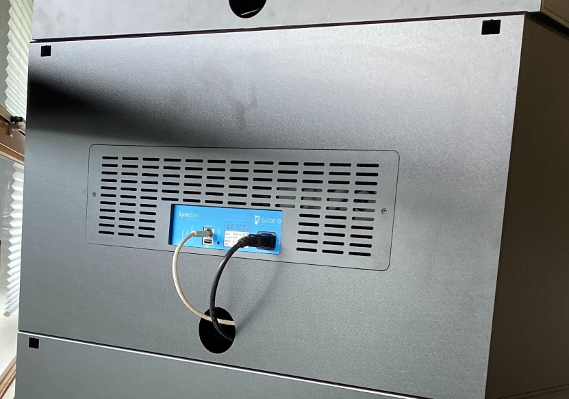
Note that when a cabinet is placed on top of another, cables may be guided internally as visible in the image below. In this case:
Power cables are combined using a (European) extension cord. The extension cord is provided by Guide ID and has a country-specific power cord
Ethernet cables are combined using a network switch, which is provided by Guide ID
2.2. Tabletop
Place the Syncbox on a flat surface, not obstructing any of the ventilation holes
Connect one or more Dockingstations to the rear of the Syncbox (see Notes on USB cabling)
Connect the Ethernet cable (or USB WiFi dongle, to the USB port combined with the Ethernet connector)
Connect the Power cable
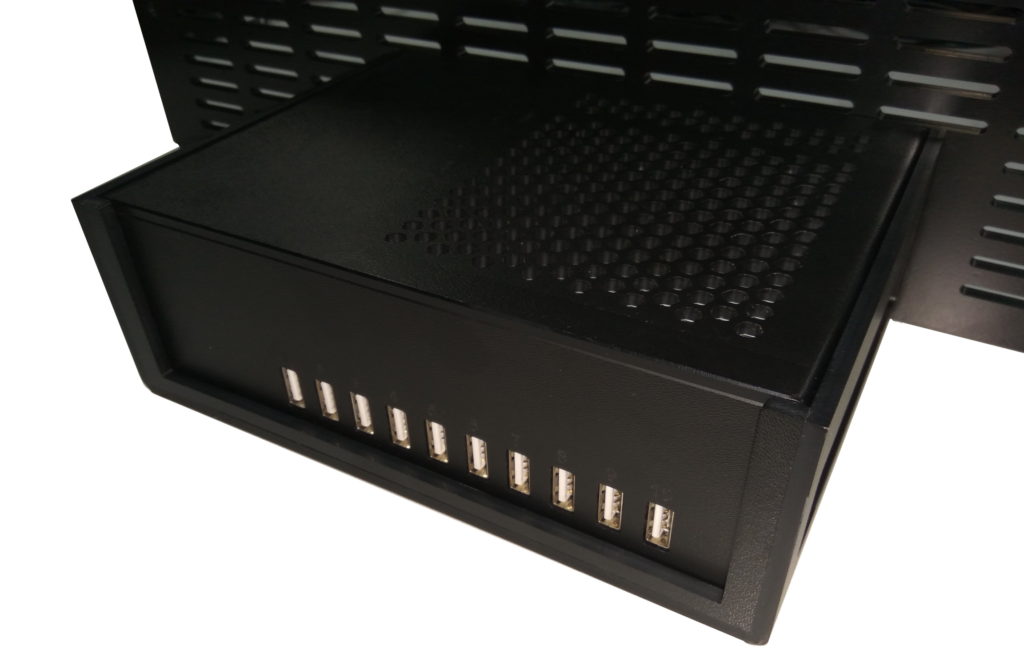
2.3. Notes on USB cabling
In both installation cases, note that the following is required for USB cabling between the Syncbox and Dockingstation:
USB Hubs are not supported. You cannot use them when connecting the Dockingstations to the Syncbox(es).
Use the USB cables supplied with the Dockingstations. When using the Syncbox to charge the Podcatchers, these cables should be less than 1m in length.
Do not use the front USB port. The Syncbox supports one Dockingstation on each of the 10 rear ports only.
To verify the cabling, after powering on the Syncbox please inspect the LED indicators on the Dockingstations. Lights should be white or green. See section Charging (5.3) for possible other LED colors.
3. Activation
The Syncbox must be activated before it becomes operational.
Notice:
Important: you cannot use a Syncconsole and a Syncbox at the same time. If you are replacing your syncconsole(s) by a Syncbox make sure to delete the syncconsole(s) first.
Beware that when switching from a Syncconsole to a Syncbox, all the published content will be re-synced on to the Podcatchers. This may take a while when you have a lot of content / multiple languages.
Activation steps:
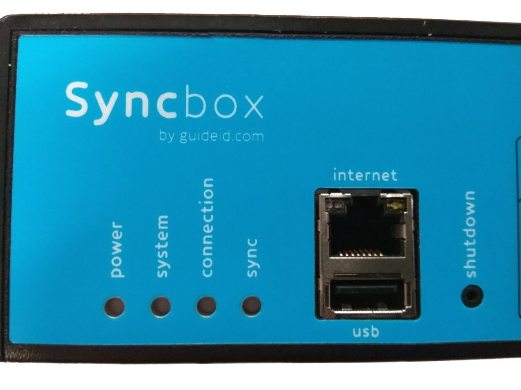
Power on the Syncbox by briefly pressing the ‘shutdown’ button
A pen may be required to reach the button
This is only required if the Syncbox was previously shut down using the button
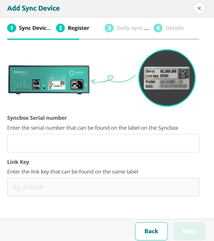
Fill in the details in the dialog. Both the Serial number and the Link key can be found on the label on your Syncbox
Your Syncbox is now ready for use!
After activation, it may take a few minutes before the Sync now button becomes available.
Select device type
Select the Syncbox
Enter Syncbox details
Enter Sync time
This represents the time that starts the automated daily sync
Enter location name
When adding multiple devices it will help you distinguish the syncboxes.
4. Usage
4.1 Power on
Briefly press the push button (labelled shutdown) to start the Syncbox, if it does not automatically switch on when power is connected. On power on the Syncbox will beep and switch on the system LED.
To verify that the Syncbox can connect to the Portal, please verify that the connection LED becomes green after connecting the Ethernet cable (or USB WiFi dongle). This can take a few minutes.
Note that when using WiFi, connecting the Syncbox to your WiFi network requires manual configuration. Please refer to advanced network configuration. Also please check this page if your network forces the use of a proxy server and does not support automatic configuration.
4.2. Service Podcatchers
Once connected and linked to your site, the Syncbox will automatically charge, synchronize and service your Podcatchers.
4.3. Shutdown for transport
When disconnected from power, the Syncbox will continue on battery power for a while. Before returning your Syncbox to Guide ID, please shut it down. In order to do so:
Press the ‘shutdown’ button for 10 seconds, until the system LED starts flashing
Wait until the system LED stops blinking
If the Syncbox is placed in a cabinet block, make sure to disconnect the USB cables and to take the Syncbox out of the cabinet holder before sending the equipment back.
5. Troubleshooting
5.1. Lights
The Syncbox has 4 dual-color LED indicators. Each of the LEDs has a separate function. If all is well, all of them should be green or green blinking. Specific information can be found in the sections below.
5.1.1. Power
Color
Blinking
Indication
Actionrequired
off
–
No power, battery is empty or Syncbox switched off
Connect power, press push button
green
no
Power connected, battery full
–
orange
no
Power connected, battery charging
–
orange
yes
No power, battery discharging
Connect power
red
yes
Power connected, battery unable to charge
Contact support
5.1.2. System
Color
Blinking
Indication
Actionrequired
off
–
System off
Connect power, press push button
green
no
System on
–
green
yes
System starting
Wait for startup
orange
no
System about to start
Wait for startup, or press button to cancel startup
orange
yes
System shutting down
If unexpected, contact support
red
no
System recovery mode
Contact support
red
yes
System overtemperature or boot error
Check temperature, if persistent contact support
5.1.3. Connection
Color
Blinking
Indication
Actionrequired
off
–
No connection (no IP address)
Check Ethernet connection and DHCP server
green
no
Connected (inactive)
–
green
yes
Connected (active)
–
orange
no
Internet (not connected to Guide ID)
Check firewall
orange
yes
Connecting
Please wait for connection. This could take a minute.
red
no
Error authenticating
Contact support
red
yes
No internet
Check internet connection or firewall, or complete WiFi configuration when dongle connected
5.1.4. Sync
Color
Blinking
Indication
Actionrequired
off
–
Sync disabled
Activate the Syncbox in the Portal
green
no
Sync finished successfully
–
green
yes
Sync running
–
orange
no
Sync scheduled
Wait for scheduled sync, or press button “Sync Now” in the Podcatcher Portal
orange
yes
Sync updating
Wait for update to complete
red
no
Sync finished with errors
Check dockingstation connections, replace faulty USB cables
5.2. Sounds
5.2.1. System state change
When the Syncbox is started or restarted, a short beep sounds once.
5.2.1. System software updates
An automated restart can happen during a system software update. This will only occur if the Syncbox is idle. In the unlikely event of a failed software update and the Syncbox being unable to continue, a long beep will sound once and the System LED will turn red. It has then entered recovery mode, requiring service from Guide ID.
5.2.2. Running on battery power
If the Syncbox becomes unpowered due to a power dip or disconnection of the main cable, it switches to battery power and will remain running for about 30 minutes. A long beep will sound every 10 seconds during this time.
If the battery is completely depleted, the Syncbox will shut down.
Note that the Dockingstations will be disconnected from the power if the Syncbox becomes unpowered (also while it still runs on battery power). The light on the top of the dockingstations will be switched off and the Podcatchers will start blinking their orange light. Once power is restored, the Syncbox and the dockingstationswill automatically resume operation.
5.2.3. Temperature range exceeded
If the Syncbox exceeds its operating temperature range, it will automatically shut down. A long beep will sound every 3 seconds during this time.
Once temperature is restored to within operational range, the Syncbox automatically resumes operation.
5.3. Charging
The Syncbox can supply power to Dockingstations through the USB cable. If Dockingstations are supplied with power, their LED on top should be green or white. If it is red, there is a problem with the connection between Syncbox and Dockingstation. Please refer to the notes on USB cabling.
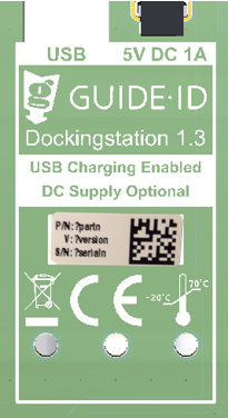
Note that only newer Dockingstationssupport USB charging:
Labelled Dockingstation 1.3. The Dockingstation version can be found on the bottom of the Dockingstation
Serialnumber of DS.005.000 and higher. The Dockingstation serial number is shown in the Sync view in the Portal.
If the Dockingstation does not support USB charging, the DC adapter must be connected.
The table below lists possible dock LED indications.
Color
Indication
off
Dockingstation is off
green
Dockingstation charging and operational
white
Dockingstation charging, not communicated yet
red
Dockingstation not charging
blue
Dockingstation locator function on (user request from Portal)
In afwachting van PP4 info- 5.4. Finding a Dockingstation
5.4. Finding a Dockingstation
If there is a problem with a specific Dockingstation, it may be required to find out where in a cabinet it has been installed. Using the portal, the LED of a Dockingstation can be temporarily set to the color blue. To accomplish this:
Check if the Dockingstation is hardware version 1.3 (supports USB charging). Please refer to section 5.3 to identify it. Dockingstation indication is not available on older hardware versions.
Open the Sync overview in the portal.
In section “Details from most recent synchronization”, beneath the Dockingstation serial, click the button labelled “ON”.
Wait until the button stops blinking. It can take up to 3 minutes for the Dockingstation LED to become blue.
The LED will remain blue for 15 minutes. You can optionally switch it off earlier using the same button on the portal. Note that again it can take up to 3 minutes for the Dockingstation LED to respond.
5.5. Helpdesk
If you have any questions, or require assistance with your Syncbox you can always contact our helpdesk.
Is the Syncbox protected against theft of customer data?
The Syncbox utilizes encrypted SSL transfers only. Periodic security patches are installed. User data is encrypted in an secondary way.
Will the Syncbox automatically power on after power loss?
The Syncbox will automatically power off when the battery is empty, and power on as soon as power is restored, unless it was switched off by the user using the push button.
6.2 ICT related
Will we ever need console access to this machine?
No. The Syncbox is a standalone device without a keyboard or monitor (headless).
Will GuideID or any 3rd parties have remote access to this machine?
No 3rd parties have access to the Syncbox. From our helpdesk, we have an option to enable remote access to the device. This will only be enabled if we need to service the device.
Can the Syncbox be put in a guest VLAN to restrict access to my Intranet?
Yes. The Syncbox only requires access to the servers listed in the Further requirements section.
Do we only need outbound internet access, no inbound NAT?
Correct. Please refer to the Further requirements section.
My network forces the use of a proxy server. Does the Syncbox support this?
Yes, but manual configuration is required if the network does not support automatic configuration, for instance because credentials must be entered. Please refer to advanced network configuration.
I have no Ethernet connection and have inserted a USB WiFi dongle. How to connect to my WiFi network?
Please refer to advanced network configuration, but note that not all WiFi dongles are supported, and can only be inserted in the USB slot combined with the Ethernet connector. Please only use the WiFi dongle supplied with the Syncbox.
When a visitor uses a Podcatcher, you can expect them to return it after use. However, some visitors may neglect, or simply forget to do so. To lower the amount of Podcatchers ‘disappearing’ over time, there are two ways to activate a warning signal built into the Podcatcher to alert visitors they should return the device. The first is a special IDentifier called the Warning IDentifier, the second is a Podcatcher setting namely the “idle time Alarm”. You can use either, neither, or both, depending on what you think is appropriate.
Warning IDentifier
The Podcatcher can sound its warning signal when it receives a Warning IDentifier code. This is a special IDentifier that is typically placed near the building exit so visitors should be notified at the right time.
The advantages of this method are that Podcatchers are more likely to be dropped off over time (especially if you have a lanyard or wristband attached), and your staff will know to ask specific visitors to return the player before leaving the building. The disadvantage is that the IR signal doesn’t go through much in the way of cloth or leather, meaning Podcatchers won’t sound the warning signal if it’s been put in a bag or pocket.
Installation of the Warning IDentifier
CAUTION: Avoid looking directly into the Warning IDentifier’s front at close range! The infrared LEDs in the device are invisible to the human eye but are very bright, especially at close range.
Testing:
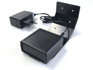
Plug the adapter into a power socket and the adapter plug into the 9V DC input on the Warning IDentifier. Although there also is a RCA connector on the back, you only need to connect the 9V DC adapter plug and nothing else.
The 2 LEDs on the back will blink green for a couple of seconds.
Then the Warning IDentifier will start transmitting alarm codes. The top LED should be red and the bottom led should flash green every time an warning signal code is transmitted (about 4x per second).
Take a Podcatcher from the Docking Station. The warning signal should sound when you are in range of the Warning IDentifier. It will sound for about 120 seconds. You can stop the warning signal sound by pressing any of the buttons on the Podcatcher, but when you are still in range it will sound again!
Configuration:
You can change the Warning IDentifier transmission power by setting the red/white switches at the back of the device. The change takes place immediately and each increase adds about 2-3 meters of range.
Switch 1 up, all others down = 25% intensity
Switch 1 and 2 up, all others down = 50% intensity
Switch 1, 2 and 3 up, all others down = 75% intensity
Switch 1, 2, 3 and 4 up, all others down = 100% intensity
Mounting:
Podcatchers can only react to the warning signal when they are in visible range of the Warning IDentifier. The Warning IDentifier sends infrared signals and infrared cannot pass through objects, therefore the Warning IDentifier works best when the Podcatcher is aimed directly at it. It is wise to place the Warning IDentifier in such a way that it is most likely to ‘reach’ a Podcatcher.
When mounting the Warning IDentifier near an exit, it is best to place it at the ceiling facing towards the visitors inside the building, so visitors that are walking towards the exit are most likely to get in range of the Warning IDentifier. When mounting near an entrance it is best to place the device in the other direction,thus facing outside of the building, because if it is facing inside, it is very likely that the Warnng IDentifier would trigger Podcatchers at the handout desk as well.
Please experiment which location and direction/angle works best to reach the Podcatchers, but not interfere with normal operations.
Warning signal after idle time
The Podcatcher can also sound an warning signal when it is engaged in a Tour but has not played audio for a while. By default this functionality is turned off, but you can set it up in the Podcatcher Site settings, under “Podcatcher idle time before alarm starts”.
The advantage of this method is that the warning signal will always sound after a while, unless properly handed in. The disadvantages are that if you set it to sound the warning signal too quickly, visitors may become annoyed; if you set it to sound the warning signal too late, the visitor may already be on the bus back home by the time it goes off. Further, if your site doesn’t collect Podcatchers in docks after visitors finish the tour (such as a drop-off box), they may start to produce a very annoying chorus over time.
Post-Alarm trigger
The Podcatcher can be made to play audio after sounding the warning signal using the Post-Alarm trigger in a stop. This will make the stop play its audio after the warning signal has stopped playing (either due to it playing for its full duration or a button being pressed). This is – as all content is – localized to the language of the tour.
Prevent missing Podcatcher
There are a number of ways to minimize the risk of losing Podcatchers. Below in the spec-sheet you’ll find a number of tips and best practices.
This article explains the network requirements and setup options for Guide-ID services in your organization. Whether you’re preparing for a new installation, adding devices, or troubleshooting connection issues, you’ll find the necessary technical specifications and configuration options here.
This article explains the network requirements and setup options for Guide-ID services in your organization. Whether you’re preparing for a new installation, adding devices, or troubleshooting connection issues, you’ll find the necessary technical specifications and configuration options here.
You’ll need this information when:
Your IT department needs to prepare the network for Guide-ID installation
You want to understand the basic network requirements before purchasing
You’re experiencing connection issues with Guide-ID devices
Your organization has specific network security policies or restrictions
You need to set up multiple Guide-ID devices across your location(s)
Connection Requirements Overview
For a working connection with Guide-ID, there are two options:
Option 1 (Recommended)
Allow access to all Guide-ID services using a single domain:
*.guide-id.com
Option 2 (Alternative)
Allow access to these specific domains:
app.guide-id.com (web application)
api.guide-id.com (basic services)
platform.guide-id.com (platform)
account.guide-id.com (login)
syncboxdebug.guideid.com (diagnostics)
Technical Requirements
Internet Connection
No port forwarding required
Outgoing access for HTTPS (TCP port 443) required
No incoming ports need to be opened
Proxy servers are supported (additional configuration may be needed)
Network Infrastructure
Wired connection (Ethernet) is preferred over WiFi
You will always receive our Podcatchers and IDentifiers with our standard Guide-ID labels. But If you would like to customize your labels you can! To do so, you can make use of our new design and ordering method.
Depending on the country you are located in, you will receive either an accountora link to a unique page where you can design and order your labels. Customers located in the Netherlands and Belgium will reveice an account from our Customer Support department. Customers located in other countries will be able to access their own unique page with a link they will receive from our Customer Support department.
Within this account / or on this page you can create, save, order and re-order your designs now and in the future. And you will also be able to order our standard Guide-ID labels and various StartIDentifiers labels you might need.
If you are already our customer and would like to order new or additional labels, you will also be able to use our new design and ordering method from now on! Please contact our Customer Support at helpdesk@guide-id.com and we will make sure to set you up.
There are several ways to minimize the risk of losing Podcatchers. In this specsheet you’ll find a number of tips and best practices.
Other ways
When a visitor uses a Podcatcher, you can expect them to return it after use. However, some visitors may neglect, or simply forget to do so. To lower the amount of Podcatchers ‘disappearing’ over time, there are several ways to activate a warning signal built into the Podcatcher to alert visitors they should return the device.
Warning IDentifier
The Podcatcher can sound its warning signal when it receives a Warning IDentifier code. This is a special IDentifier that is typically placed near the building exit so visitors should be notified at the right time.
Warning signal after idle time
The Podcatcher can also sound an warning signal when it is engaged in a Tour but has not played audio for a while. By default this functionality is turned off, but you can set it up in the Site Podcatcher settings, under “Podcatcher idle time before alarm starts”.
The advantage of this method is that the warning signal will always sound after a while, unless properly handed in. The disadvantages are that if you set it to sound the warning signal too quickly, visitors may become annoyed; if you set it to sound the warning signal too late, the visitor may already be on the bus back home by the time it goes off. Further, if your site doesn’t collect Podcatchers in docks after visitors finish the tour (such as a drop-off box), they may start to produce a very annoying chorus over time.
Post-Alarm trigger
The Podcatcher can be made to play audio after sounding the warning signal using the Post-Alarm trigger in a stop. This will make the stop play its audio after the warning signal has stopped playing (either due to it playing for its full duration or a button being pressed). This is – as all content is – localized to the language of the tour.
Sometimes, our Podcatchers need some extra attention, for example when they get into an errormode. If this is the case, the LED light on the Podcatcher will show you. Our new and updated manual will help you prevent Podcatchers going into an error state and explain what the LED light is telling you and which action to take. The manual combines the information in 3 languages; Dutch, English and French. User manual
The Syncbox is a compact computer, designed by Guide ID to charge and synchronize Podcatcher audio guides. You can connect up to 10 dockingstations (100 Podcatchers) to one Syncbox.