AV-Sync is an innovative feature that enhances the way audiences enjoy multimedia presentations. With AV-Sync, audio content is perfectly synchronized with video content. This means an unlimited amount of visitors can watch a video displayed on a screen and listen to the corresponding audio track on a Podcatcher, all in real-time and in their preferred language.
By offering multiple language accommodation, AV-Sync ensures that every visitor, regardless of their language preference, can have a fully immersive, personalized, and synchronized audiovisual experience.
Enabling AV-Sync
This guide walks you through the process of setting up AV-Sync, ensuring compatibility, preparing and testing your files, and conducting a flawless tour. What we will achieve is extracting the existing audio track from the video and replacing it with a time code. The original audio track will be transferred to the Podcatchers, allowing visitors to listen in real-time. Don’t worry, the original video will stay intact.
Step 1: Preparing the Movie File
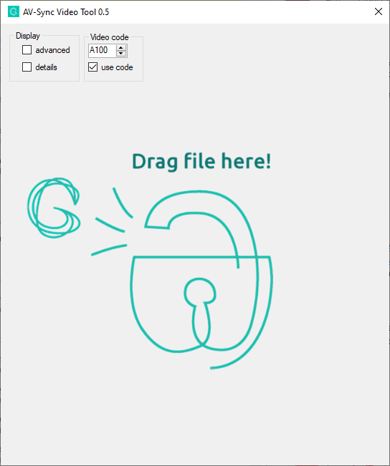
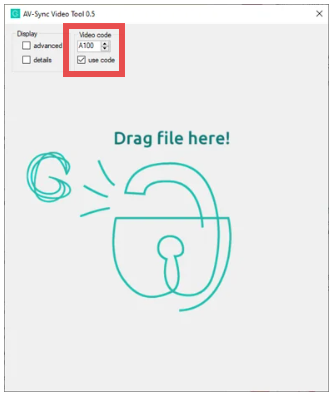
Use the Guide-ID AV-Sync Tool to process your original movie file. Assign a unique Video Code to each movie file – starting with “A1”. Make sure that the ‘Use Code’ check box is checked. The tool generates two files: one for video playback on the media player and an audio file to be uploaded to the Guide-ID Portal.
Both files will be exported to your computer next to the original video. The audio file ends with “_audio” the video with the added timecode end with “_video”.
Log into the Guide-ID Platform, and create a new AV-Sync stop. Upload the audio file generated by the AV-Sync Tool. If you have alternate languages for the tour, upload these audio files as well. They should have the same length as the original audio.
Enter the Video Code you’ve chosen in the tool in the Video Code box. Also add an IDentifier that visitors can scan.
Step 3: Test the Video Playback
Begin playing the video on the media player to ensure it is displayed correctly on the screen.
You will note a beeping sound, don’t worry. This beep is translated by the Brainbox to a time code.
Make sure that the volume on the media player is unmuted and set to an appropriate level, ensuring it is neither too quiet nor too loud.
Setting the volume to 30 or 40 % is mostly perfect.
Step 4: Brainbox Setup
Now, connect the supplied cables:
Use a 3.5mm Jack cable to connect the media player (or TV) to the Brainbox.
Use the IR Out connector to connect the RCA cable to the supplied AV-Sync IDentifier with the Brainbox
Connect the USB-C cable to the power adapter or use a USB-A port on the media player.
Both the led’s (WiFi and AV-Sync) blink Orange once.
Press the small switch button on the Brainbox.
The AV-Sync LED will turn orange. Indicating Auto Gain has started where the Brainbox is searching for the best setting. The LED light will flash green within around 15 seconds; all done.
Step 5: Test the Tour
Lastly, ensure that your tour is published and synced on the Guide-ID Platform. Test the tour’s audio by playing the AV-Sync stop on the Podcatcher or holding your phone close to the IDentifier if using an app. Point the Podcatcher or phone at the AV-Sync IDentifier and ensure the expected audio starts playing, indicating a successful setup.
Following these steps will provide a seamless and enjoyable tour experience for your audience, further enhanced with the power of synchronized multimedia delivered by AV-Sync.
Understanding the LED Indicators on Your Brainbox
Make sure the Brainbox is connected to a mediaplayer with a running video
color AV-Sync LED
Meaning
Green blinking
the AV-Sync signal is functioning correctly, ensuring perfect audio-video synchronization.
Orange (1 short blink)
The Brainbox is powered on.
Orange
Auto gain is in progress. It’s fine-tuning the settings for optimal audio synchronization. it’s started and stopped by pressing the switch button. If it takes more than 15 seconds you need to check the audio volume of the media player. Make sure it’s unmuted and not too quiet.
Red blinking
The Brainbox is receiving an audio input, but it’s not the correct AV-Sync track. Test the audio output of the media player with headphones or speakers to check if you can hear the AV-Sync track (beeping noises at regular intervals).If you don’t hear the beeps, the AV-Sync track isn’t added to the video or the audio output isn’t selected on the player. Alternatively, the audio track was added to the left channel.Alternative, adjust the volume by lowering is 20 %. restart the auto gain by pressing the switch button.
off
No audio signal is being processed. Verify the volume on the media player. Note, when plugging in the USB-C cable it wil blink orange once indicating it’s powered.
Remember, the Brainbox doesn’t need a Wi-Fi connection to work; it just needs power (through a USB-C 5V adapter) and the correct audio signal from a media player. With AV-Sync, your visitors can enjoy videos in perfect harmony with audio, in real-time and in any language. Setting up your Brainbox is the first step to offering an immersive and synchronized audiovisual experience!
To give you a good impression on how to add an AV-Sync stop in your tour, we have made a short video. It briefly takes you through the steps; how to prepare the video, what to do in the Toureditor and how to connect the hardware. Detailed information can of course be found in the AV-Sync IDentifier articles on this helppage.
As soon as you have made your tour in the Podcatcher Portal you can install the received hardware. Haven’t you made your tour yet? or need instructions? please have a look at this page; getting started
Installing the hardware
Connecting the IDentifiers
You can finalize your tour by connecting the IDentifiers (triggers) to the stops in the tour. You need to connect at least one IDentifier to each stop in your tour. Every IDentifier has a unique number which you can find on the back of the IDentifier (for example EF:FF:FF:43).
There will be 1 or more IDentifiers with a language/country flag, these need to be connected as a Start IDentifier for the different languages in which you provide the tour. (Note; you need a different IDentifier for each language).
When all the stops are added in the tour (have an IDentifier connected and contain an audio file) you need to “publish” the new tour. After that you can mount the IDentifiers next to the objects in the exhibition.
The rest of the installation is very simple;
Connecting the Synbox to the portal
First you need to connect the Syncbox to your site in the portal:
Open the Portal and login to your account
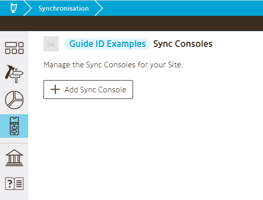
Select the Sync module on the left
Click the button “Add Sync Console”
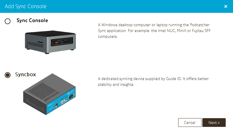
Select Syncbox as device type
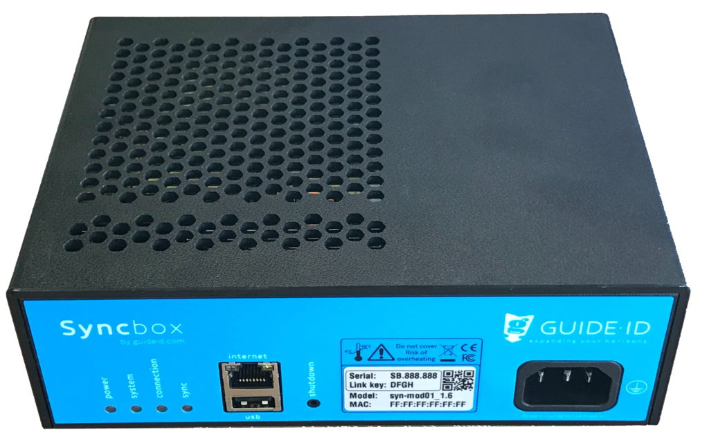
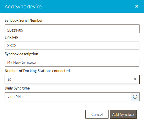
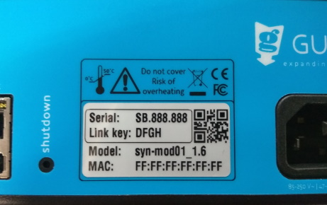
Fill in the details in the dialog. Both the Serial number and the Link key can be found on the label on your Syncbox
Your Syncbox is now ready for use!
Connecting the Dockingstation and the Syncbox
Now you can connect the Dockingstation and the Syncbox:
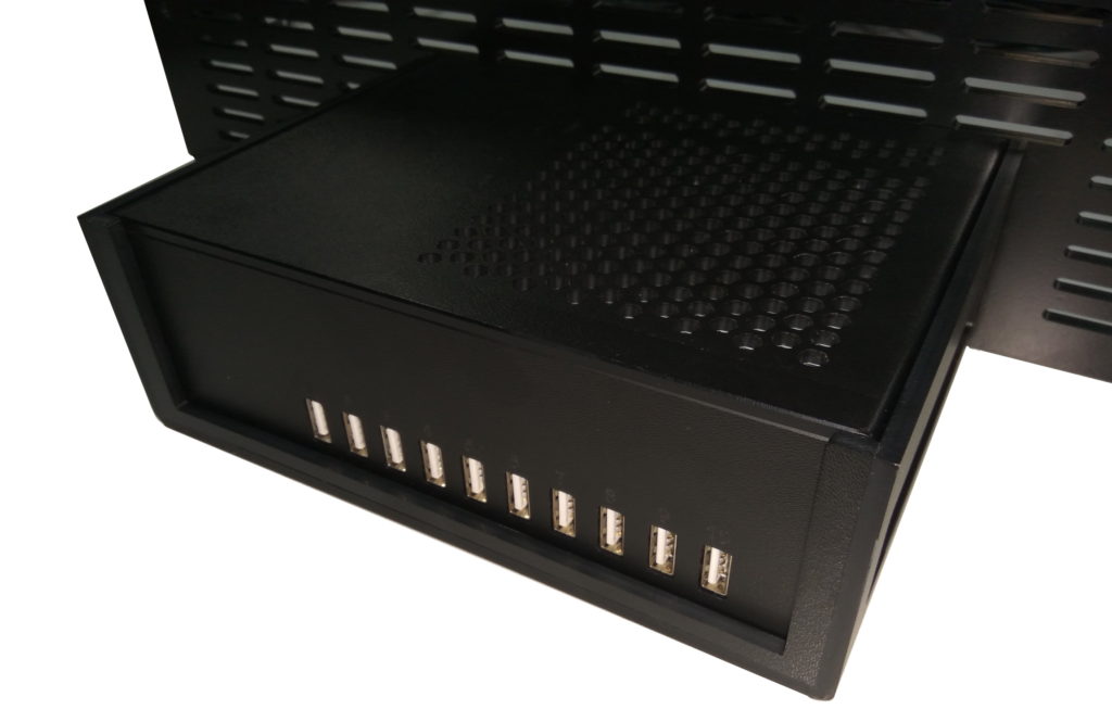
Connect the Dockingstation to the Syncbox that we have provided into one of the 10 available USB ports on the front, and plug everything into the power socket.
Insert the Podcatchers firmly in the Dockingstation
Connect the Syncbox to a wired internet connection using the USB port on the back (note the whole set up needs to stay connected to power and internet 24/7)
Start the Syncbox
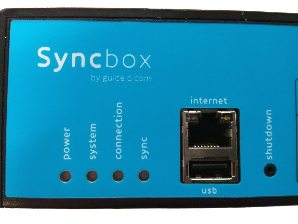
Power on the Syncbox by briefly pressing the ‘shutdown’ button
A pen may be required to reach the button
This is only required if the Syncbox was previously shut down using the button
Log on to the Podcatcher Portal, go to “sync” and press Sync Now.
Now the content will be synced on to the Podcatchers, one after another
When a Podcatcher light turns green, you can take it out and start testing your new tour.
Every day our server connects with the Syncbox, to ensure updates are written on to the Podcatchers, to restore Podcatchers which have an error and to retrieve the logs and statistics from the Podcatchers to add to the Analytics.
The AV-Sync Testmode is a Podcatcher mode which gives acces to 2 AV-Sync specific features to setup your AV-Sync clips. The mode is used for the following cases:
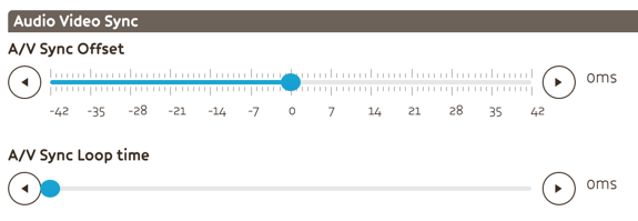
To determine the desired AV-Sync offset
Measure an estimate for the AV-Sync loopdelay.
Note: when you are already content with the synchronization between the Podcatcher audio and the video, you do not require these features.
Usage
The AV-Sync testmode is activated by removing the Podcatcher from the dock whilst holding the middle (B) and right (C) buttons at the same time. The testmode is recognised by the yellow led which blinks together with the green led when a tour is started.
AV-Sync offset
The AV-Sync offset is used to adjust the synchronization between the Podcatcher audio and the video by playing the audio a fraction earlier or later.
The following instructions explain how the testmode is used to determine the desired AV-Sync offset value.
Aim the Podcatcher, in AV-Sync testmode, at the AV-Sync IDentifier.
Use the left and right buttons to in- or decrease the AV-Sync offset on the Podcatcher. After every press the value is pronounced* .When pressing the middle button the value is reset to 0.
Re-aim the Podcatcher to the AV-Sync IDentifier. The audio will now be played with the selected AV-Sync offset. Notice the red led which indicated the audio is played with an offset.
Repeat from step 2 until you are happy with the synchronization.
Press the middle button while audio is playing to pronounce the last used offset value. Enter this value as AV-Sync offset for this AV-Sync clip.
* Minus is pronounced as “Foxtrot”
AV-Sync loopdelay
With the AV-Sync loopdelay the audio can be brought back in sync after a loop, by delaying the audio.
The following instruction explain how the AV-Sync testmode is used to make an estimate for the desired loopdelay value.
Aim the Podcatcher, in AV-Sync testmode, at the AV-Sync IDentifier.
Await the video loop and aim at the AV-Sync IDentifier again around 10 seconds in the video.
The Podcatcher will pronounce an estimate of the desired loopdelay value. Enter this value as AV-Sync loopdelay for this AV-Sync clip.
Due technical limitations the Podcatcher cannot determine the exact value. Try the following to make a better estimate of the required value:
Await multiple video loops before the 2nd scan of the AV-Sync IDentifier, and divide the pronounced value by the amount of loops.
Perform multiple measurements and take the average.
Test the synchronization after setting the loopdelay, publishing and syncing. Adjust the value with little steps in case you are not yet happy with the synchonization.
Note: PC’s do not have a constant loop time when used for video playback. Use a dedicated media player for constant video looping.
We have made a video in which we show you how to add the newly received IDentifiers to your new tour and how to install the setup with loose, new Dockingstations and a Syncbox.
Sometimes, our Podcatchers need some extra attention, for example when they get into an errormode. If this is the case, the LED light on the Podcatcher will show you. Our new and updated manual will help you prevent Podcatchers going into an error state and explain what the LED light is telling you and which action to take. The manual combines the information in 3 languages; Dutch, English and French. User manual
The Syncbox is a compact computer, designed by Guide ID to charge and synchronize Podcatcher audio guides. You can connect up to 10 dockingstations (100 Podcatchers) to one Syncbox.
We recommend using a wired network connection whenever available. In cases where it isn’t, but you have a WiFi network available, you can connect the Syncbox to it using a USB WiFi dongle.
Only specific types of dongles are supported, so please contact our helpdesk if you are in need of one. Configuration must be repeated for each USB dongle. If you have more than one Syncbox, you may be provided with a WiFi access point instead, to simplify the configuration and provide the best reception.
1.1. USB WiFi dongle
Connecting the Syncbox to WiFi using a USB dongle is an easy one-time process. Follow the steps below.
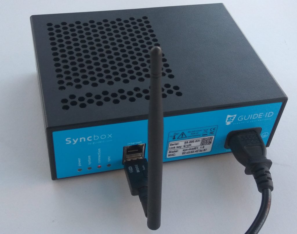
1. Insert the USB dongle into the front USB port that is below the Ethernet port, and startup you Syncbox. Note: Do not use any of the 10 USB ports on the rear of the Syncbox for the WiFi dongle. The device will not be found.
Step 1: Connect the WiFi dongle
2. Wait for about 2 minutes, until the connection LED starts flashing red. This indicates that the Syncbox has started a WiFi hotspot.
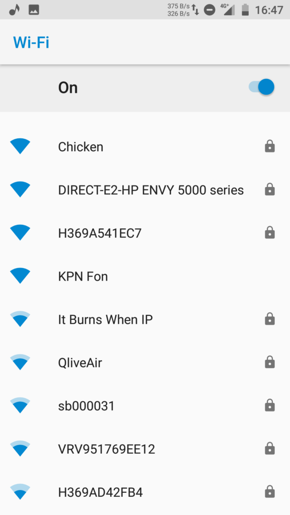
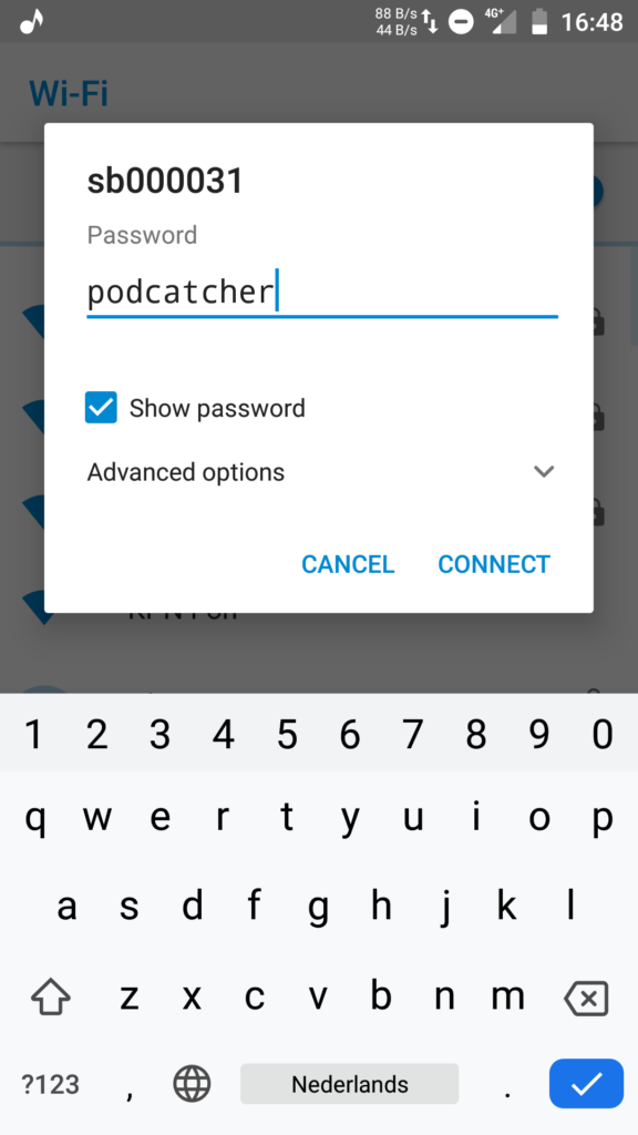
3. Search for WiFi networks on you phone (or another WiFi capable device). Select the network named after the label on you Syncbox, and connect to it. The WiFi password is “podcatcher”.
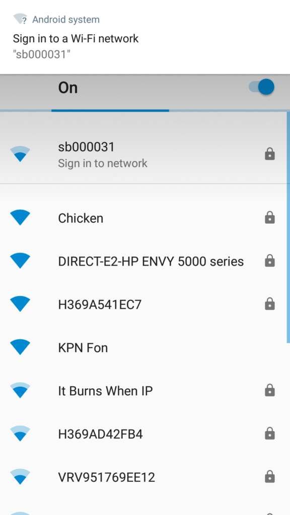
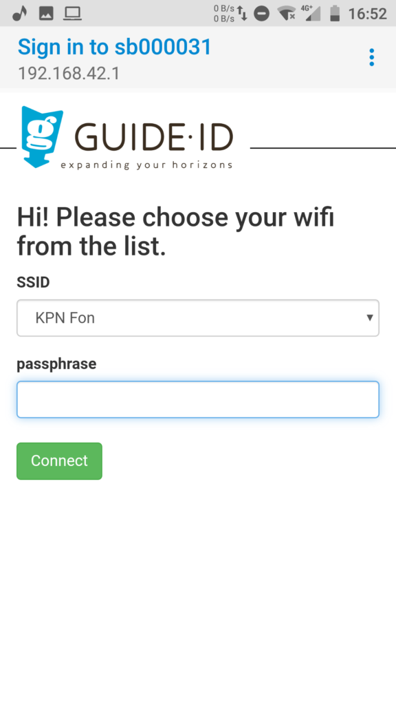
4. When you are connected to the hotspot, a popup should be shown: “Sign in to network”. Click on it to open the WiFi configuration page.
5. Select your WiFi network from the drop down list. Enter the passphrase, and click “Connect”. The WiFi hotspot will be disabled, and the Syncbox will connect to your WiFi network.
To check if the connection is succesfull, observe the connection LED. The LED should be blinking orange, and become green after about one minute. If there is an error connecting to the WiFi network, the LED will return to blinking red and the hotspot will be restarted. You can then go back to step 3.
1.2. WiFi access point
Instead of using a WiFi dongle for each Syncbox, it is possible to use an access point in client mode to connect many Syncboxes to your wireless network at once. The Syncboxes connect to the access point by means of Ethernet cables, and the access point is configured to connect to your wireless network. To help plan your setup, please contact our helpdesk.
Configuration using a WiFi access point is similar to the procedure for connecting a single USB dongle. But, you will only have to configure the access point.
2. Proxy server
On some locations it is required to access the internet through a proxy server. The Syncbox supports proxy servers through automatic and manual configuration. There are however some requirements on the type of proxy server used.
2.1. Proxy server requirements
Your proxy server must meet the following requirements:
Support HTTPS connections to websites. Or in technical terms: support the HTTP CONNECT method, where the proxy server sets up a direct connection between the client and the website. As most websites today use HTTPS, most proxy servers support this feature. Some proxy servers however require clients to install a special certificate, instead of using HTTP CONNECT. This is currently not supported by the Syncbox.
If your proxy server requires entering a username and password to access the internet, this is supported by the Syncbox, but currently only through the HTTP basic authentication scheme. Other existing types (e.g. HTTP Digest, HTTP NTLM and HTTP Negotiate) are currently not supported.
2.2. Automatic configuration (WPAD)
The Syncbox supports automatic configuration of a proxy server by means of the Web Proxy Auto-Discovery Protocol (WPAD). If your network is configured to support this, proxy server configuration of the Syncbox is done automatically and will work out of the box.
If your proxy server requires entering a username and password to access the internet, automatic configuration will normally not provide the Syncbox with these credentials. To enter them you would need to resort to manual configuration. As an alternative you can include the credentials in the the proxy URL in the PAC file. An example PAC file in this format is shown below.
function FindProxyForURL(url, host)
{
   return "PROXY username:password@192.168.1.1:8080; DIRECT";
}
Note: Including the username and password for the proxy server in the PAC file will make it available to all users on the network, unless access to the PAC file is regulated by for instance IP address. The MAC address of the Syncbox is printed on its label to allow to assigning it a specific IP address.
3. Manual configuration
Manual configuration of Syncbox network settings is possible using a USB mass storage device. Please follow the steps below.
3.1. Prepare the USB stick
Format a USB stick in FAT format.
Create a new text file on it named “config”. The file must not be placed within a directory.
Add configuration entries to the file as specified below.
3.2. Network configuration entries
The configuration file “config” can contain a combination of the following configuration entries, each on a separate line.
3.2.1. General
Clear all network profiles config_net_reset=1
Note: The reset can be combined with other entries and will be handled first.
3.2.2. Wireless LAN
WiFi ssid to apply settings to (if omitted, configure Ethernet) config_net_wifi_ssid=My WiFi Network
WiFi password to install config_net_wifi_pass=password
WiFi auth-alg: – open: Open System – shared: Shared Key config_net_wifi_auth=open
Note: Proxy configuration applies to wired Ethernet, unless it is combined with wireless LAN configuration entries. To manually configure a proxy server for WiFi, you must also manually configure the WiFi settings. If you have already used the hotspot method to configure WiFi, you must clear the existing profile using the reset option listed above.
Proxy server host config_net_proxy_host=192.168.1.1
Proxy server port config_net_proxy_port=8080
Proxy server username config_net_proxy_user=username
Proxy server password config_net_proxy_pass=password
3.3. Apply settings on a Syncbox
Using the following steps you can apply the configuration to a Syncbox. You can repeat these steps on multiple Syncboxes, using the same USB stick.
Power off the Syncbox, by holding the “Shutdown” button 10 seconds until the system LED starts blinking orange and finally switches off.
Insert the USB stick into the front USB port below the Ethernet connector. Note: Do not use any of the 10 USB ports on the rear of the Syncbox for the USB stick. The device will not be found.
Press and hold the “Shutdown” button for 10 seconds to start it in recovery mode. The Syncbox should apply the settings, and automatically reboot to normal mode. Note 1: Release the button when the system LED becomes orange. If you hold it too long it becomes red and will start in a different mode. Note 2: If applying the settings failed or no settings were applied, the Syncbox will stay in recovery mode and the system LED will stay red. In this case check the USB device, and restart at step 1 to retry.
Two steps are required to prepare your video for use with AV-Sync:
Prepare the video file (replace the audio with the AV-Sync track). The video file will play on your mediaplayer.
Prepare the audio file (split off the audio from the video to a MP3 file). The audio file will be uploaded in the TourEditor to be played on the Podcatcher.
Creating these files is an automatic process when using the video tool.
For more information on the usage of the tool, or for detailed instructions on how to do the media file preparation manually, please refer to the following sections.
2. AV-Sync video tool
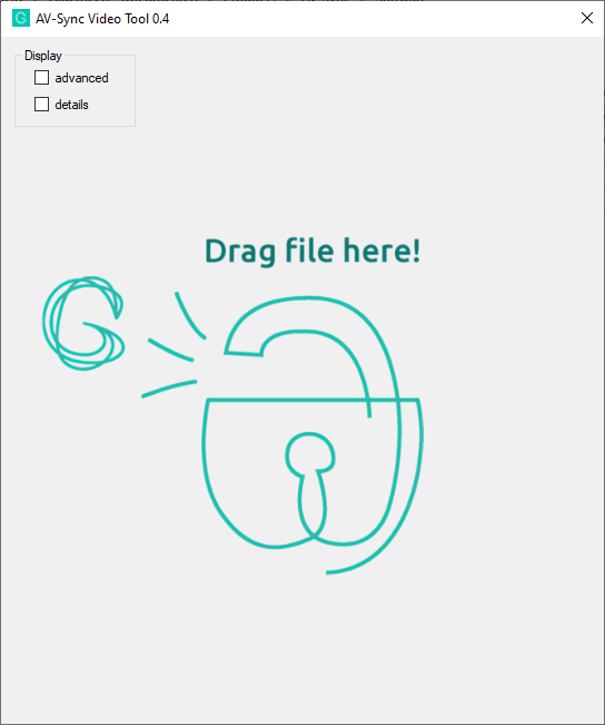
The easiest way to prepare you media files is by using the AV-Sync video tool. You can download it here:
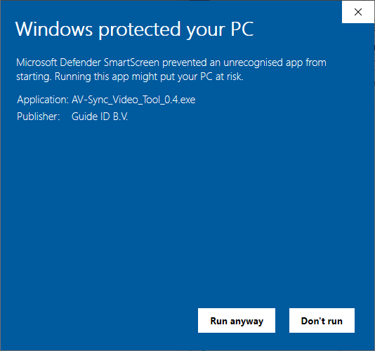
Note: When opening the program, you may see the message “Windows protected your PC”. Please click the button “Run anyway” to continue.
You can drag and drop any video on the tool, and it will create two new files in the same directory as the input file:
<inputfilename>_video.mp4
<inputfilename>_audio.mp3
The video file is to be placed on your mediaplayer. The audio file is to be uploaded in the TourEditor, to play on the Podcatchers.
2.1. Advanced video settings
If the advanced checkbox has not been selected, the video tool will use settings that suit most cases. If it has been selected, the following video options are available:
Convert: This checkbox enables conversion of the video. When unchecked, the video content is ‘multiplexed’ into the output file unmodified. This means that video resolution and quality will remain unchanged. When checked, video is transcoded to the h264 codec. Note that conversion may be automatically enabled, if your video is encoded using a video codec that is not supported in MP4 files. If so, the progress will indicate “Converting video”.
Flexcode: This checkbox enables the IDentifier code input field to be used for flexible mode AV-Sync videos. Please refer to the AV-Sync manual for details.
Room audio: If unchecked, the output video will contain the AV-Sync track instead of the original audio. If checked, the original audio is converted to a single channel and added to the output video as well. The output video will contain a stereo audio track, with the AV-Sync track on the right, and the original audio on the left channel. This makes it possible to still play the original audio in the room with the video, in addition to hearing the audio on the Podcatchers.
2.2. Advanced audio settings
If the advanced checkbox has not been selected, the video tool will use settings that suit most cases. If it has been selected, the following audio options are available:
Bitrate: Choose the bitrate for the audio to be played on the Podcatchers. Note that a higher bitrate improves the quality, but also the time required to sync the Podcatchers. We advice a bitrate of 64k for mono, and 128k for stereo. If left to auto, the encoder uses the input file to choose the best bitrate for you.
Channels: Choose the amount of channels for the audio to be played on the Podcatchers. If the input file contains stereo audio, you may choose to reduce it to mono. This way the bitrate can be reduced, reducing the sync time per Podcatcher. Using stereo is advised when using headphones.
Extend: This input field allows extending the audio file with silence for the specified time. This could be used for loop correction, however preferably use the slider in the tour editor to configure this: see “Fine tuning” in the AV-Sync manual.
The Syncbox is a compact computer, designed by Guide ID to charge and synchronize Podcatcher audio guides. You can connect up to 10 dockingstations (100 Podcatchers) to one Syncbox. If you have more Podcatchers on location you will need multiple Syncboxes.
The Syncbox is IEC 62368 certified. However the following safety requirements apply:
Use the Syncbox only within the specified operating temperature range (0-50 C).
Do not cover the ventilation openings. Risk of overheating.
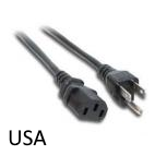
Use the provided AC power cable only.
Connect AC cable to an earthed mains socket outlet or extension cord.
Mains socket outlet must be easily accessible to allow disconnecting the cable.
Ethernet port is intended for LAN connection installed wholly within the same building structure.
The Syncbox contains a Lithium-Ion battery (750 mAh, 3.7V, AA format). The battery is IEC 62133 certified.
Caution:
Do not replace the battery. Risk of explosion if the battery is replaced by an incorrect type.
Disposal of the battery into fire or a hot oven, or mechanically crushing or cutting of a battery, can result in an explosion.
Leaving the battery in an extremely high temperature environment can result in an explosion or the leakage of flammable liquid or gas.
Subjecting the battery to extremely low air pressure may result in an explosion or leakage of flammable liquid or gas.
1.5. Requirements
Important: The Syncbox must be connected to power and internet 24 hours per day, 7 days a week.
To connect the Syncbox you will need:
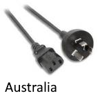
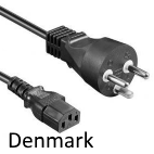
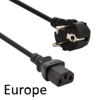
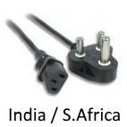
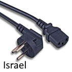
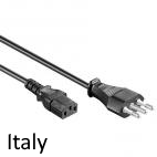
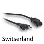
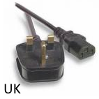
Available power outlet (country specific AC Power cord is provided)
Internet connection, by means of either:
Ethernet cable or free socket (CAT5 or CAT6 standard)
WiFi network (IEEE802.11n / g / b, 2.4 GHz bands)
1.5.1. Power
If power is removed, the Syncbox will continue on battery power for about half an hour. It will indicate this by beeping periodically. See Running on battery power.
1.5.2. Internet
If internet is disconnected, the Syncbox will remain functional for a maximum of 2 days. However contact with the Portal is not possible.
The internet connection has the following requirements:
Fully functional internet access to websites (HTTPS).
If you have multiple devices, a Router with DHCP is required. For multiple Syncboxes built into cabinets, a network switch is provided to make them share a single connection.
If you have a firewall, outgoing access to HTTPS (TCP port 443) is required. The Syncbox uses only outgoing connections on that port. No port forwarding is required for incoming connections. Whitelisted domains should include:
syncboxapi.guideid.com
syncboxlogs.guideid.com
syncboxdebug.guideid.com
Using an Ethernet cable is recommended above using a WiFi network. Connecting the Syncbox to your WiFi network requires manual configuration. Please refer to advanced network configuration.
Internet access through proxy servers is supported, but may require manual configuration. Please refer to advanced network configuration.
2. Installation
2.1. In a cabinet
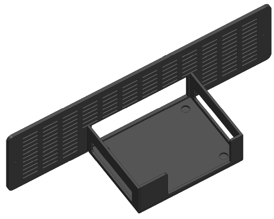
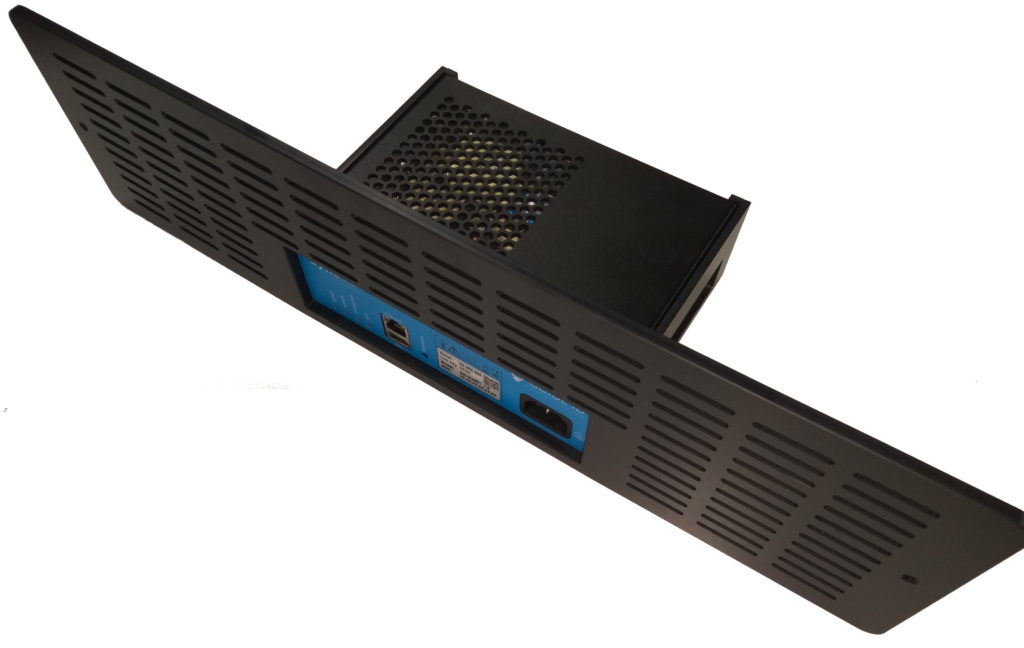
On the rear of the cabinet, remove the cabinet holder (2 screws)
Place the Syncbox in the cabinet holder
Guide the 10 dockingstation USB cables out of the cabinet, and connect them to the rear of the Syncbox (see Notes on USB cabling)
Mount the cabinet holder (2 screws)
Connect the Ethernet cable (or USB WiFi dongle, to the USB port combined with the Ethernet connector)
Connect the Power cable
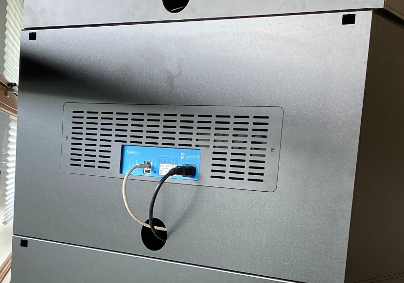
Note that when a cabinet is placed on top of another, cables may be guided internally as visible in the image below. In this case:
Power cables are combined using a (European) extension cord. The extension cord is provided by Guide ID and has a country-specific power cord
Ethernet cables are combined using a network switch, which is provided by Guide ID
2.2. Tabletop
Place the Syncbox on a flat surface, not obstructing any of the ventilation holes
Connect one or more Dockingstations to the rear of the Syncbox (see Notes on USB cabling)
Connect the Ethernet cable (or USB WiFi dongle, to the USB port combined with the Ethernet connector)
Connect the Power cable
2.3. Notes on USB cabling
In both installation cases, note that the following is required for USB cabling between the Syncbox and Dockingstation:
USB Hubs are not supported. You cannot use them when connecting the Dockingstations to the Syncbox(es).
Use the USB cables supplied with the Dockingstations. When using the Syncbox to charge the Podcatchers, these cables should be less than 1m in length.
Do not use the front USB port. The Syncbox supports one Dockingstation on each of the 10 rear ports only.
To verify the cabling, after powering on the Syncbox please inspect the LED indicators on the Dockingstations. Lights should be white or green. See section Charging (5.3) for possible other LED colors.
3. Activation
The Syncbox must be activated before it becomes operational.
Notice:
Important: you cannot use a Syncconsole and a Syncbox at the same time. If you are replacing your syncconsole(s) by a Syncbox make sure to delete the syncconsole(s) first.
Beware that when switching from a Syncconsole to a Syncbox, all the published content will be re-synced on to the Podcatchers. This may take a while when you have a lot of content / multiple languages.
Activation steps:
Power on the Syncbox by briefly pressing the ‘shutdown’ button
A pen may be required to reach the button
This is only required if the Syncbox was previously shut down using the button
Fill in the details in the dialog. Both the Serial number and the Link key can be found on the label on your Syncbox
Your Syncbox is now ready for use!
After activation, it may take a few minutes before the Sync now button becomes available.
Add Sync ConsoleSelect device typeEnter Syncbox detailsFind serial number and link key on the label
4. Usage
4.1 Power on
Briefly press the push button (labelled shutdown) to start the Syncbox, if it does not automatically switch on when power is connected. On power on the Syncbox will beep and switch on the system LED.
To verify that the Syncbox can connect to the Portal, please verify that the connection LED becomes green after connecting the Ethernet cable (or USB WiFi dongle). This can take a few minutes.
Note that when using WiFi, connecting the Syncbox to your WiFi network requires manual configuration. Please refer to advanced network configuration. Also please check this page if your network forces the use of a proxy server and does not support automatic configuration.
4.2. Service Podcatchers
Once connected and linked to your site, the Syncbox will automatically charge, synchronize and service your Podcatchers.
4.3. Shutdown for transport
When disconnected from power, the Syncbox will continue on battery power for a while. Before returning your Syncbox to Guide ID, please shut it down. In order to do so:
Press the ‘shutdown’ button for 10 seconds, until the system LED starts flashing
Wait until the system LED stops blinking
If the Syncbox is placed in a cabinet block, make sure to disconnect the USB cables and to take the Syncbox out of the cabinet holder before sending the equipment back.
5. Troubleshooting
5.1. Lights
The Syncbox has 4 dual-color LED indicators. Each of the LEDs has a separate function. If all is well, all of them should be green or green blinking. Specific information can be found in the sections below.
5.1.1. Power
Color
Blinking
Indication
Actionrequired
off
–
No power, battery is empty or Syncbox switched off
Connect power, press push button
green
no
Power connected, battery full
–
orange
no
Power connected, battery charging
–
orange
yes
No power, battery discharging
Connect power
red
yes
Power connected, battery unable to charge
Contact support
5.1.2. System
Color
Blinking
Indication
Actionrequired
off
–
System off
Connect power, press push button
green
no
System on
–
green
yes
System starting
Wait for startup
orange
no
System about to start
Wait for startup, or press button to cancel startup
orange
yes
System shutting down
If unexpected, contact support
red
no
System recovery mode
Contact support
red
yes
System overtemperature or boot error
Check temperature, if persistent contact support
5.1.3. Connection
Color
Blinking
Indication
Actionrequired
off
–
No connection (no IP address)
Check Ethernet connection and DHCP server
green
no
Connected (inactive)
–
green
yes
Connected (active)
–
orange
no
Internet (not connected to Guide ID)
Check firewall
orange
yes
Connecting
Please wait for connection. This could take a minute.
red
no
Error authenticating
Contact support
red
yes
No internet
Check internet connection or firewall, or complete WiFi configuration when dongle connected
5.1.4. Sync
Color
Blinking
Indication
Actionrequired
off
–
Sync disabled
Activate the Syncbox in the Portal
green
no
Sync finished successfully
–
green
yes
Sync running
–
orange
no
Sync scheduled
Wait for scheduled sync, or press button “Sync Now” in the Podcatcher Portal
orange
yes
Sync updating
Wait for update to complete
red
no
Sync finished with errors
Check dockingstation connections, replace faulty USB cables
5.2. Sounds
5.2.1. System state change
When the Syncbox is started or restarted, a short beep sounds once.
5.2.1. System software updates
An automated restart can happen during a system software update. This will only occur if the Syncbox is idle. In the unlikely event of a failed software update and the Syncbox being unable to continue, a long beep will sound once and the System LED will turn red. It has then entered recovery mode, requiring service from Guide ID.
5.2.2. Running on battery power
If the Syncbox becomes unpowered due to a power dip or disconnection of the main cable, it switches to battery power and will remain running for about 30 minutes. A long beep will sound every 10 seconds during this time.
If the battery is completely depleted, the Syncbox will shut down.
Note that the Dockingstations will be disconnected from the power if the Syncbox becomes unpowered (also while it still runs on battery power). The light on the top of the dockingstations will be switched off and the Podcatchers will start blinking their orange light. Once power is restored, the Syncbox and the dockingstationswill automatically resume operation.
5.2.3. Temperature range exceeded
If the Syncbox exceeds its operating temperature range, it will automatically shut down. A long beep will sound every 3 seconds during this time.
Once temperature is restored to within operational range, the Syncbox automatically resumes operation.
5.3. Charging
The Syncbox can supply power to Dockingstations through the USB cable. If Dockingstations are supplied with power, their LED on top should be green or white. If it is red, there is a problem with the connection between Syncbox and Dockingstation. Please refer to the notes on USB cabling.
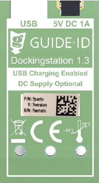
Note that only newer Dockingstationssupport USB charging:
Labelled Dockingstation 1.3. The Dockingstation version can be found on the bottom of the Dockingstation
Serialnumber of DS.005.000 and higher. The Dockingstation serial number is shown in the Sync view in the Portal.
If the Dockingstation does not support USB charging, the DC adapter must be connected.
The table below lists possible dock LED indications.
Color
Indication
off
Dockingstation is off
green
Dockingstation charging and operational
white
Dockingstation charging, not communicated yet
red
Dockingstation not charging
blue
Dockingstation locator function on (user request from Portal)
5.4. Finding a Dockingstation
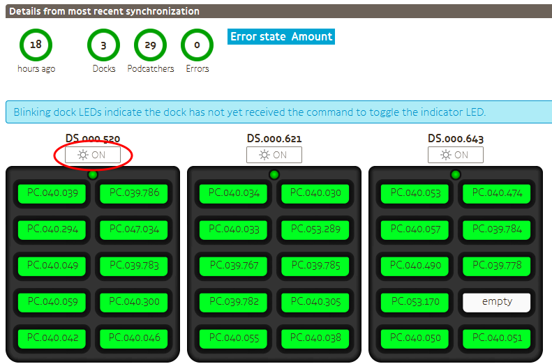
If there is a problem with a specific Dockingstation, it may be required to find out where in a cabinet it has been installed. Using the portal, the LED of a Dockingstation can be temporarily set to the color blue. To accomplish this:
Check if the Dockingstation is hardware version 1.3 (supports USB charging). Please refer to section 5.3 to identify it. Dockingstation indication is not available on older hardware versions.
Open the Sync overview in the portal.
In section “Details from most recent synchronization”, beneath the Dockingstation serial, click the button labelled “ON”.
Wait until the button stops blinking. It can take up to 3 minutes for the Dockingstation LED to become blue.
The LED will remain blue for 15 minutes. You can optionally switch it off earlier using the same button on the portal. Note that again it can take up to 3 minutes for the Dockingstation LED to respond.
5.5. Helpdesk
If you have any questions, or require assistance with your Syncbox you can always contact our helpdesk.
Is the Syncbox protected against theft of customer data?
The Syncbox utilizes encrypted SSL transfers only. Periodic security patches are installed. User data is encrypted in an secondary way.
Will the Syncbox automatically power on after power loss?
The Syncbox will automatically power off when the battery is empty, and power on as soon as power is restored, unless it was switched off by the user using the push button.
6.2 ICT related
Will we ever need console access to this machine?
No. The Syncbox is a standalone device without a keyboard or monitor (headless).
Will GuideID or any 3rd parties have remote access to this machine?
No 3rd parties have access to the Syncbox. From our helpdesk, we have an option to enable remote access to the device. This will only be enabled if we need to service the device.
Can the Syncbox be put in a guest VLAN to restrict access to my Intranet?
Yes. The Syncbox only requires access to the servers listed in the Further requirements section.
Do we only need outbound internet access, no inbound NAT?
Correct. Please refer to the Further requirements section.
My network forces the use of a proxy server. Does the Syncbox support this?
Yes, but manual configuration is required if the network does not support automatic configuration, for instance because credentials must be entered. Please refer to advanced network configuration.
I have no Ethernet connection and have inserted a USB WiFi dongle. How to connect to my WiFi network?
Please refer to advanced network configuration, but note that not all WiFi dongles are supported, and can only be inserted in the USB slot combined with the Ethernet connector. Please only use the WiFi dongle supplied with the Syncbox.
 English
  Nederlands
  Français