Preventing your Podcatchers from going missing
Introduction
When a visitor uses a Podcatcher, you can expect them to return it after use. However, some visitors may neglect, or simply forget to do so. To lower the amount of Podcatchers ‘disappearing’ over time, there are two ways to activate a warning signal built into the Podcatcher to alert visitors they should return the device. The first is a special IDentifier called the Warning IDentifier, the second is a Podcatcher setting namely the “idle time Alarm”. You can use either, neither, or both, depending on what you think is appropriate.
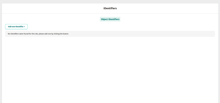
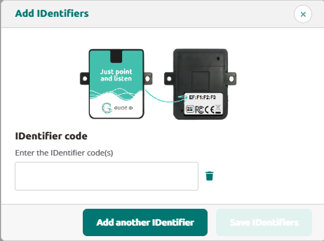
Warning IDentifier
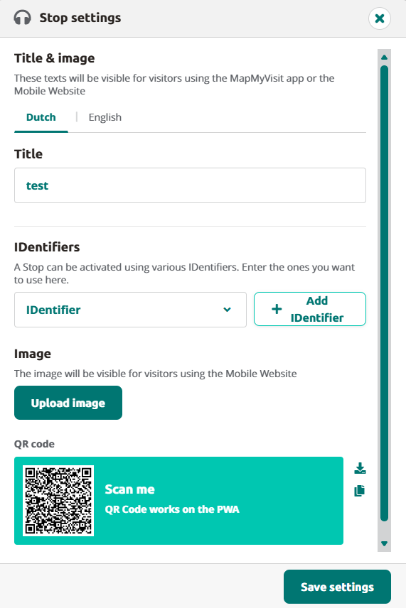
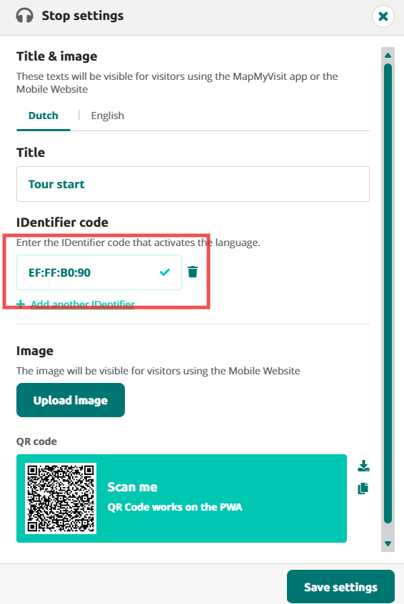
The Podcatcher can sound its warning signal when it receives a Warning IDentifier code. This is a special IDentifier that is typically placed near the building exit so visitors should be notified at the right time.
The advantages of this method are that Podcatchers are more likely to be dropped off over time (especially if you have a lanyard or wristband attached), and your staff will know to ask specific visitors to return the player before leaving the building.
The disadvantage is that the IR signal doesn’t go through much in the way of cloth or leather, meaning Podcatchers won’t sound the warning signal if it’s been put in a bag or pocket.
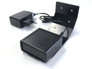
Installation of the Warning IDentifier
CAUTION: Avoid looking directly into the Warning IDentifier’s front at close range! The infrared LEDs in the device are invisible to the human eye but are very bright, especially at close range.
Testing:
- Plug the adapter into a power socket and the adapter plug into the 9V DC input on the Warning IDentifier. Although there also is a RCA connector on the back, you only need to connect the 9V DC adapter plug and nothing else.
- The 2 LEDs on the back will blink green for a couple of seconds.
- Then the Warning IDentifier will start transmitting alarm codes. The top LED should be red and the bottom led should flash green every time an warning signal code is transmitted (about 4x per second).
- Take a Podcatcher from the Docking Station. The warning signal should sound when you are in range of the Warning IDentifier. It will sound for about 120 seconds. You can stop the warning signal sound by pressing any of the buttons on the Podcatcher, but when you are still in range it will sound again!
Configuration:
You can change the Warning IDentifier transmission power by setting the red/white switches at the back of the device.
The change takes place immediately and each increase adds about 2-3 meters of range.
Switch 1 up, all others down = 25% intensity
Switch 1 and 2 up, all others down = 50% intensity
Switch 1, 2 and 3 up, all others down = 75% intensity
Switch 1, 2, 3 and 4 up, all others down = 100% intensity
Mounting:
Podcatchers can only react to the warning signal when they are in visible range of the Warning IDentifier. The Warning IDentifier sends infrared signals and infrared cannot pass through objects, therefore the Warning IDentifier works best when the Podcatcher is aimed directly at it. It is wise to place the Warning IDentifier in such a way that it is most likely to ‘reach’ a Podcatcher.
When mounting the Warning IDentifier near an exit, it is best to place it at the ceiling facing towards the visitors inside the building, so visitors that are walking towards the exit are most likely to get in range of the Warning IDentifier. When mounting near an entrance it is best to place the device in the other direction,thus facing outside of the building, because if it is facing inside, it is very likely that the Warnng IDentifier would trigger Podcatchers at the handout desk as well.
Please experiment which location and direction/angle works best to reach the Podcatchers, but not interfere with normal operations.
Warning signal after idle time
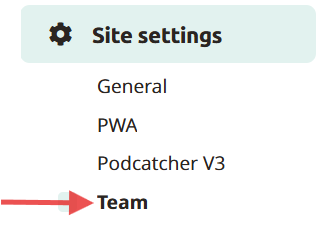
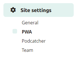
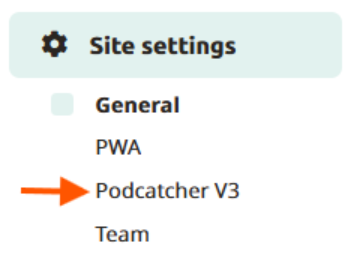
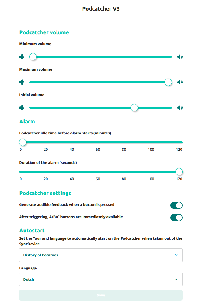
The Podcatcher can also sound an warning signal when it is engaged in a Tour but has not played audio for a while. By default this functionality is turned off, but you can set it up in the Podcatcher Site settings, under “Podcatcher idle time before alarm starts”.
The advantage of this method is that the warning signal will always sound after a while, unless properly handed in. The disadvantages are that if you set it to sound the warning signal too quickly, visitors may become annoyed; if you set it to sound the warning signal too late, the visitor may already be on the bus back home by the time it goes off. Further, if your site doesn’t collect Podcatchers in docks after visitors finish the tour (such as a drop-off box), they may start to produce a very annoying chorus over time.
Post-Alarm trigger
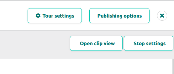
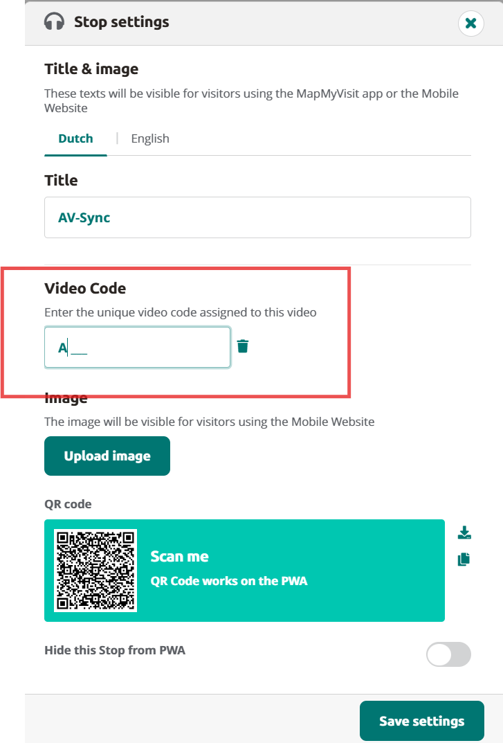
The Podcatcher can be made to play audio after sounding the warning signal using the Post-Alarm trigger in a stop. This will make the stop play its audio after the warning signal has stopped playing (either due to it playing for its full duration or a button being pressed). This is – as all content is – localized to the language of the tour.
Prevent missing Podcatcher
There are a number of ways to minimize the risk of losing Podcatchers. Below in the spec-sheet you’ll find a number of tips and best practices.
Prevent missing Podcatcher
-1.png?width=242&height=242&name=6%20(1)-1.png)
.png?width=390&height=389&name=1%20(1).png)
.png?width=390&height=390&name=2%20(1).png)
.png?width=390&height=389&name=3%20(1).png)
.png?width=390&height=389&name=4%20(1).png)
.png?width=390&height=389&name=5%20(1).png)

